Quantcast
Viewing all 203 articles
Browse latest View live

Eversolar Eversol Solar Inverter Fault & Error Messages

Image may be NSFW.
Clik here to view.
Eversolar Eversol Solar Inverter
For an Eversolar Eversol Solar Inverter, performing a proper shutdown procedure can already fix some minor issues. But there are some errors that involve doing some specific steps. Gold Coast Power Solutions have put together a list of faults, displays and possible actions in case you experience any of the problems below.

As a tip, you will recognize a fault on an Eversolar Eversol Solar Inverter by the red LED that will light up instead of the green LED. It will also show one of the LCD display messages below.

View the Eversolar Eversol Solar Inverter user manual here.

Fault

LCD Display

Possible actions

Resumable Fault Isolation Fault 1. Check the impedance is between PV (+) & PV
(-) and the PV-Inverter is earthed. The impedance must be greater than 2MΩ
2. If the problem persists please call service
Ground I Fault 1. The ground current is too high.
2. Unplug the inputs from the PV generator and
check the peripheral AC system
3. After the cause is cleared, re-plug the PV panel and check PV-Inverter status.
4. If the problem persists please call service.
Grid Fault
Fac Over Range
Vac Over Range
1. Wait for 5 minutes, if the grid returns to normal, PV-Inverter automatically restarts.
2. Make sure grid voltage and frequency meet the specifications
3. If the problem persists please call service
Utility Loss 1. Grid is not connected.
2. Check grid connection cables.
3. Check grid usability. 4. If grid is ok, and the problem persists, maybe the fuse in the inverter is open, please call service.
Over Temperature 1. The internal temperature is higher than
specified normal value
2. Find a way to reduce the ambient temperature.
3. Or is move the inverter to a cooler environment
4. If it not effective, call local service
PV over Voltage 1. Check the open PV voltage, see if it is greater than or too close to 500VDC
2. If PV voltage is less than 500VDC, and the
problem still occurs, please call local service
Permanent Fault Consistent Fault 1. Disconnect PV (+) or PV (-) from the input,
restart the PV-Inverter
2. If it does not work, call service
Relay Failure
DC INJ High
EEPROM R/W Fail
SCI Failure
AC HCT Fault
GFCI Failure
1. Disconnect ALL PV (+) or PV (-)
2. Wait for few seconds
3. After the LCD switches off, reconnect and
check again
4. If the message reappears, please contact
local service

Image may be NSFW.
Clik here to view.
Eversolar Eversol Solar Inverter
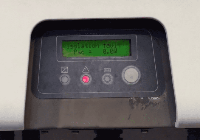
The full details are available in the Eversolar Eversol Solar Inverter manual’s Troubleshooting section. If the issue continues after following the actions above, check if your Eversolar Eversol Solar Inverter is still within the 5-year warranty period so the issue can be covered. However, if the inverter is outside warranty, we suggest you contact a professional solar power expert. If you’re in the Gold Coast or Brisbane area contact Gold Coast Power Solutions here so our team can provide you with further assistance.

View the Eversolar Eversol Solar Inverter user manual here.

Image may be NSFW.
Clik here to view.
Need a quality solar inverter? We deliver Australia wide

Got A Question About Solar Power? Click Here For Answers!

The post Eversolar Eversol Solar Inverter Fault & Error Messages appeared first on Gold Coast Solar Power Solutions.


Eaton ETN2000 Solar Inverter Fault & Error Messages

Image may be NSFW.
Clik here to view.
Eaton ETN2000 Solar Inverter
The Eaton ETN2000 solar inverter can develop a number of different faults and when a fault is present an error message will be displayed on the screen and usually the fault light will be lit. Below is a list of error messages, explanations on the error or fault and a list of possible actions to take to resolve the issue.

View the Eaton ETN2000 Solar Inverter manual here.

Fault

Display

Possible actions

System Fault Ground I Fault 1. The ground current is too high.
2. Unplug the inputs from the PV generator and check the peripheral AC system
3. After the cause is cleared, re-plug the PV panel and check PV-Inverter status.
4. If the problem persists please call service.
Grid Fault 1. Wait for 5 minutes, if the grid returns to normal, PV-Inverter automatically restarts.
2. Make sure grid voltage and frequency meet the specifications
3. If the problem persists please call service
No Utility 1. Grid is not connected.
2. Check grid connection cables.
3. Check grid usability.
Inverter Failure PV over Voltage 1. Check the open PV voltage, see if it is greater than or too close to 500VDC
2. If PV voltage is less than 500VDC, and the
problem still occurs, please call local service
Consistent Fault 1. Disconnect PV (+) or PV (-) from the input,
restart the PV-Inverter
2. If it does not work, call service
Over Temperature 1. The internal temperature is higher than
specified normal value
2. Find a way to reduce the ambient temperature.
3. Or move the inverter to a cooler environment
4. If it is not effective, call local service
Relay Failure
DC INJ High
EEPROM
Failure
SCI Failure
High DC Bus
Low DC Bus
Ref 2.5V Fault
DC Sensor
Fault
GFCI Failure
1. Disconnect ALL PV (+) or PV (-)
2. Wait for few seconds
3. After the LCD switches off, reconnect and check again
4. If the message reappears, please contact Eaton.

Here are some error messages and descriptions that you may see on the Eaton ETN2000 Solar Inverter display screen.

Operating conditions

In English

Description

System Fault
Isolation failure Isolation fault Earth fault of the PV-panels or failure of surge voltage protection
GFCI active Ground I fault Leakage current detected from ground conductor is too high
Grid failure Grid fault Grid measured data is beyond the specification (voltage & frequency)
No utility No Utility Utility is not available
Input voltage too high PV over voltage Input voltage is higher than the maximum input voltage
Inverter Fault
Consistent failure Consistent Fault The readings of 2 microprocessors are not consistent. It could be caused by CPU and/or other circuits do not function well.
Temperature too high Over temperature The internal temperature of inverter higher than normal value
Output relay failure Relay Failure The relay between inverter and functional
Output DC injection too high DC INJ High Output DC injection is higher than expected
EEPROM problem EEPROM Failure EEPROM inside has data access problem
Communication failure between microprocessors Communication failure SCI Failure The communication between MCU inside is abnormal
DC bus voltage is too high High DC Bus The DC BUS voltage is higher than expected
DC bus voltage is too low Low DC Bus The DC BUS voltage is lower than expected
2.5V reference voltage inside problem Ref 2.5V Fault The 2.5V reference inside are abnormal
Output DC sensor abnormal DC Sensor Fault Detection of DC output sensor is abnormal
GFCI detection problem GFCI Failure The GFCI detection circuit is abnormal

For more details checkout the Eaton ETN2000 Solar Inverter manual’s Troubleshooting section. If you still have an issue after following the recommendations listed above we recommend that you contact a professional solar power expert. If you’re in the Gold Coast or Brisbane area contact Gold Coast Power Solutions here and we will be in touch to provide you with further assistance.

View the Eaton ETN2000 Solar Inverter manual here.

Image may be NSFW.
Clik here to view.
Need a quality solar inverter? We deliver Australia wide

Got A Question About Solar Power? Click Here For Answers!


The post Eaton ETN2000 Solar Inverter Fault & Error Messages appeared first on Gold Coast Solar Power Solutions.

Delta Solivia Solar Inverter Fault & Error Messages

Image may be NSFW.
Clik here to view.
delta solivia solar inverter error codes and fault messages
The Delta Solivia range of solar inverters can develop a number of different faults, when a fault is present an error message will be displayed on the screen and usually one or a number of the LED’s will be lit. Below is a list of error messages, explanations on the error or fault and a list of actions to take to resolve the issue.

The LEDs on the front panel of the inverter display the operational state of the solar inverter. These are:

  • LED (A): Operation – displays the operational state.
  • LED (B): Earth Fault – displays an insulation resistance fault or PV grounding (GND) fault on the DC side.
  • LED (C): Failure – displays existing faults internally or externally and whether the grid feed-in operation has been interrupted.

If you have one of the error or fault messages below we recommend you follow the listed actions to take to remove the fault before contacting a company who can help you further such as Gold Coast Solar Power Solutions.

View the Delta Solivia Solar Inverter manual here.

LED STATUS

 DISPLAY MESSAGE CAUSE

ACTION TO TAKE

green: <on>
red: <on>
yellow: <on>
Display communication
faulty.
 If the fault persists after the device has been reset, please inform your service technician.
green: <off>
red: <off>
yellow: <on>
AC frequency failure Grid frequency overshooting or undershooting specified limit range.  Check the grid frequency via the display in the N (NOW) menu.
green: <off>
red: <off>
yellow: <on>
AC voltage
failure
Grid voltage overshooting
or undershooting specified
limit range.
Check the grid voltage via the display in the N menu.
If no voltage present, check grid
automatic circuit breaker.
green: <off>
red: <off>
yellow: <on>
AC relay
failure
One of the anti-islanding
protection output relays is
faulty / defective.
The solar inverter is defective.
Return the device.
green: <flashes>
red: <off>
yellow: <off>
Calibration
ongoing
Check internal settings. Normal function before input mode.
green: <off>
red: <off>
yellow: <on>
DC injection
failure
DC component of input-
side alternating current is
too high.
If the fault persists after the device has been reset, please inform your service
technician.
green: <off>
red: <off>
yellow: <on>
Error # 301 Internal communication
error or hardware fault.
If the fault persists after the device has  been reset, please inform your service
technician.
green: <off>
red: <off>
yellow: <on>
Error # 302 The device trips and
reverts to grid input mode
once the temperature has
dropped.
Check the installation site (no direct
sunlight, air circulation).
green: <off>
red: <on>
yellow: <off>
Error # 506
Error # 508
Isolation resistance fault
on the DC side during
start-up phase (# 508) or
running phase (# 506).
Check the isolation resistance on the DC side of the PV modules.
green: <on>
red: <on>
yellow: <off>
Isolation start up warning
Isolation running warning
Isolation resistance fault
on the DC side during
start-up phase or running
phase.
You must check the isolation resistance on the DC side of the PV modules.
Solar inverter is still feeding!
green: <on>
red: <on>
yellow: <off>
PV+ grounding fault
PV- grounding fault
Connection PV+ (PV-)
to GND is interrupted or
wrong pole is connected
to GND.
Check that the GND connection has been
made correctly and/or check the fuse in
the grounding path. Change the fuse if
necessary. The solar inverter remains in
feed-in operation.
green: <off>
red: <off>
yellow: <on>
Revision error Versions of hard and software are not compatible. If the fault persists after the device has
been reset, please inform your service
technician.
green: <on>
red: <on>
yellow: <on>
Self-test ongoing Initialization of solar inverter on start-up. The first time the solar inverter is started up: Normal function with a PV cell voltage
of between 100 V and 150 V.
green: <flashes>
red: <off>
yellow: <off>
PV power too low Insufficient input power. Insufficient insolation (dawn/twilight).
Check the PV cell voltage via the
display in the N menu.
green: <flashes>
red: <off>
yellow: <off>
PV voltage too low PV generator voltage between 100 V and 150 V. Insufficient insolation.
Check the PV cell voltage via the
display in the N menu.
green: <flashes>
red: <off>
yellow: <off>
Synchronize to AC Checks grid voltage and
grid frequency for grid
input mode.
Normal function before input mode.
green: <on>
red: <off>
yellow: <flashes>
Varistor warning Internal varistor at the DC
input is defective.
Although you can, in theory, carry on
using the solar inverter, the varistors
should be replaced at the earliest
opportunity. This will involve returning the device.

Image may be NSFW.
Clik here to view.
Delta Solivia Solar Inverter
For further details check out the Delta Solivia Solar Inverter manual here. The Delta Solivia range of inverters came came with a 10 year warranty against defects so if the instructions above hasn’t rectified the error the best thing to do is to contact the company who installed your inverter originally. If your inverter is outside the warranty period you will need to talk to a local solar accredited electrician for further assistance such as Gold Coast Solar Power Solutions.

If you’re in the Gold Coast or Brisbane area contact Gold Coast Power Solutions as our solar power experts will be able to provide you with further assistance.

Image may be NSFW.
Clik here to view.
Need a quality solar inverter? We deliver Australia wide

Got A Question About Solar Power? Click Here For Answers!

The post Delta Solivia Solar Inverter Fault & Error Messages appeared first on Gold Coast Solar Power Solutions.

CMS-2000 Solar Inverter Fault and Error Messages

Image may be NSFW.
Clik here to view.
CMS-2000 Solar Inverter
The CMS 1500 and CMS 2000 solar inverters can develop a number of different faults and when a fault is present an error message will be displayed on the screen and usually the fault light will be lit. The below is a list of error messages, explanations on the error or fault and a list of possible actions to take to resolve the issue.

View the CMS-2000 Solar Inverter manual here.

Fault

Display

Possible actions

System

Fault

Isolation Fault 1. Check the impedance is between PV (+) & PV (-) and the PV-Inverter is earthed. The impedance must be greater than 8MΩ.
2. If the problem persists please call service.
Ground I Fault 1. The ground current is too high.
2. Unplug the inputs from the PV generator and
check the peripheral AC system.
3. After the cause is cleared, re-plug the PV panel
and check PV-Inverter status.
4. If the problem persists please call service.
Grid Fault 1. Wait for 5 minutes, if the grid returns to normal,
PV-Inverter automatically restarts.
2. Make sure grid voltage and frequency meet the
specifications.
3. If the problem persists please call service.
No Utility 1. Grid is not connected.
2. Check grid connection cables.
3. Check grid usability.
Inverter

Failure

PV over Voltage 1. Check the open PV voltage, see if it is greater
than or too close to 500VDC.
2. If PV voltage is less than 500VDC, and the
problem still occurs, please call local service.
Consistent Fault 1. Disconnect PV (+) or PV (-) from the input,
restart the PV-Inverter.
2. If it does not work, call service.
Over Temperature 1. The internal temperature is higher than
specified normal value
2. Find a way to reduce the ambient temperature,
3. Or move the inverter to a cooler environment.
4. If it is not effective, call local service.
Relay Failure
DC INJ High
EEPROM
Failure
SCI Failure
High DC Bus
Low DC Bus
Ref 2.5V Fault
DC Sensor
Fault
GFCI Failure
1. Disconnect ALL PV (+) or PV (-)
2. Wait for few seconds
3. After the LCD switches off, reconnect and
check again.
4. If the message reappears call your local service.


Image may be NSFW.
Clik here to view.
CMS-2000 Solar Inverter
For more information on the CMS inverter range you can check out the CMS-2000 Solar Inverter manual under the Inverter Status and Troubleshooting sections. Unfortunately the manufacturer of the CMS-2000 Solar Inverter has been placed in receivership so if you own one of these inverters unfortunately you are left without a warranty. If you are in the Gold Coast or Brisbane area contact Gold Coast Power Solutions here and our team will provide you with further assistance. If you’re somewhere else around Australia and have an issue with your CMS 2000 or CMS 1500 solar inverter we can send you a quality replacement inverter with free delivery, just click on the image below.

View the CMS-2000 Solar Inverter manual here.

Image may be NSFW.
Clik here to view.
Need a quality solar inverter? We deliver Australia wide

Got A Question About Solar Power? Click Here For Answers!

The post CMS-2000 Solar Inverter Fault and Error Messages appeared first on Gold Coast Solar Power Solutions.

Ginlong Solis Solar Inverter Fault & Error Messages

Image may be NSFW.
Clik here to view.
Ginlong Solis Solar Inverter
Ginlong Solis Solar Inverter is a value-priced brand of inverters manufactured in China. Due to the high range of faults that Chinese inverters are known for there’s not a lot of reputable solar installing companies that offer this inverter.

But if you find that there’s a fault in your Ginlong Solis Solar Inverter, we have put together a list of faults, descriptions and actions from the Ginlong Solis user manual for your quick reference.

For this inverter the LCD screen will display an alarm message in case of failure. When this happens the inverter may stop feeding into the grid. Here are the failure descriptions and their corresponding alarm messages.

Alarm Message Failure description Proper Shutdown Procedure
OV-G-V Over grid voltage If the inverter displays any alarm message on this list, turn off the inverter and wait for 5 minutes before restarting it. Refer to the instructions below to stop and start your inverter. If the failure persists, please contact your local distributor or the service center.

To stop the Inverter, the following steps must be strictly followed:

1. Switch the Grid Supply Main Switch (AC) OFF.

2. Wait 30 seconds. Switch the DC Isolator OFF. All the LEDs of the inverter will be off in a minute.

To start up the Inverter, it is important that the following steps are strictly followed:

1. Switch the Solar Supply Main Switch (AC) ON first.

2. Switch the DC Isolator ON. If the voltage of PV arrays is higher than start up voltage, the inverter will turn on. The red LED power will light, and the LCD shows the company’s name and the inverter model.

3. When both the DC and the AC grid sides supply to the inverter, it will be ready to generate power. Initially, the inverter will check both its internal parameters and the parameters of the AC grid, to ensure that they are within the acceptable limits. At the same time, the green LED will flash and the LCD displays the information of INITIALIZING.

4. After 30-180 seconds (depending on local requirement), the inverter will start to generate power. The green LED will be on continually and the LCD displays GENERATING.

UN-G-V Under grid voltage
OV-G-F Over grid frequency
UN-G-F Under grid frequency
G-IMP High grid impedance
NO-GRID No grid voltage
OV-DC Over DC voltage
OV-BUS Over DC bus voltage
UN-BUS Under DC bus voltage
GRID-INTF. Grid interference
INI-FAULT Initialization system fault
OV-TEM Over Temperature
GROUND-FAULT Ground fault
ILeak-FAULT High Grid leakage current
Relay-FAULT Relay check fault
DCinj-FAULT High DC injection current

The full information is available in the Ginlong Solis solar inverter manual’s troubleshooting section. In case performing the steps above does not fix the issue and your Ginlong Solis Solar Inverter is still within the warranty period you can contact the equipment installer or supplier. Be ready with the serial number, installation date, description of the issue and system design for the PV array configuration (e.g. number of panels, capacity of panels, number of strings, etc.).

If your inverter is outside the warranty period we suggest that you contact a professional solar power expert. If you’re in the Gold Coast or Brisbane area contact Gold Coast Power Solutions here and we will be in touch to provide you with further assistance.

Image may be NSFW.
Clik here to view.
Need a quality solar inverter? We deliver Australia wide

Got A Question About Solar Power? Click Here For Answers!

The post Ginlong Solis Solar Inverter Fault & Error Messages appeared first on Gold Coast Solar Power Solutions.

Growatt SunGold Solar Inverter Fault & Error Messages

Image may be NSFW.
Clik here to view.
Growatt SunGold Solar Inverter
Since Growatt SunGold Solar Inverter is a Chinese brand, you will expect that it is certainly cheaper than European inverters on the market. In terms of performance, you can also say that they are better than their Chinese counterparts. But it is inevitable to encounter some issues.

Thus, we have put together a list of fault displays and possible action from Growatt SunGold Solar Inverter user manual for your easy reference.

Should any problems arise on your Growatt SunGold solar inverter, the LED on the front panel will be red and the LCD displays the relevant information. If you encounter any of these issues and decide to follow the recommended actions below, please note that safety measures should be observed to avoid any risk of injury.

Fault

Display

Possible Action

SYSTEM FAULT Ground I Fault 1. The ground current is too high.

2. Unplug the inputs from the PV generator and check the peripheral AC system.

3. After the cause is cleared, re-plug the PV panel and check PV-Inverter status.

4. If the problem persists please call service.

Isolation Fault 1. Check the impedance is between PV (+) & PV (-) and the PV-Inverter is earthed. The impedance must be greater than 8M.

2. If the problem persists please call service.

Grid Fault 1. Wait for 5 minutes, if the grid returns to normal, PV-Inverter automatically restarts.

2. Make sure grid voltage and frequency meet the specifications.

3. If the problem persists please call service.

4. Check grid usability.

No AC connection 1. Grid is not connected.

2. Check grid connection cables.

INVERTER FAILURE PV Over Voltage 1. Check the open PV voltage; see if it is greater than or too close to 500VDC.

2. If PV voltage is less than 500VDC, and the problem still occurs, please call local service.

Consistent Fault 1. Disconnect PV (+) or PV (-) from the input, restart the PV-Inverter.

2. If it does not work, call service. If there is no display on the panel, please check PV-input connections. If the voltage is higher than 150V, call your local service.

During periods of little or no sunlight, the PV-Inverter may continuously start up and shut down. This is due to insufficient power generated to operate the control circuits.


Here are some more fault messages that you may see on the Growatt SunGold front panel display.

FAULT

DISPLAY

OPERATION

System Fault Auto Test Failed Auto test do not pass
No AC Connection No utility; no grid connect
PV Isolation Low Insulation problem
Residual High GFCI Fault
Output High DCI Output current DC, offset too high
PV Voltage High PV panel voltage too high
AC V Outrange Grid voltage out of range
AC F Outrange Grid frequency out of range
Inverter Fault Error: 100 2.5 V Reference Voltage Fault
Error: 101 Communication Fault
Error: 102 Consistent Fault
Error: 116 EEPROM Fault
Error: 117 Relay Fault
Error: 118 Init Model Fault
Error: 119 GFCI Device Damage
Error: 120 HCT Fault
Error: 121 Communication Fault
Error: 122 Bus Voltage Fault

The full information is available in the Growatt SunGold solar inverter manual’s troubleshooting section. If following the steps above does fix the issue and your Growatt SunGold inverter is still within the warranty period you can contact the equipment installer or supplier.

If your inverter is outside the warranty period we suggest that you contact a professional solar power expert. If you’re in the Gold Coast or Brisbane area contact Gold Coast Power Solutions here and we will be in touch to provide you with further assistance.

Image may be NSFW.
Clik here to view.
Need a quality solar inverter? We deliver Australia wide

Got A Question About Solar Power? Click Here For Answers!

The post Growatt SunGold Solar Inverter Fault & Error Messages appeared first on Gold Coast Solar Power Solutions.

Growatt MTL Solar Inverter Fault & Error Messages

Image may be NSFW.
Clik here to view.
Growatt MTL Solar Inverter
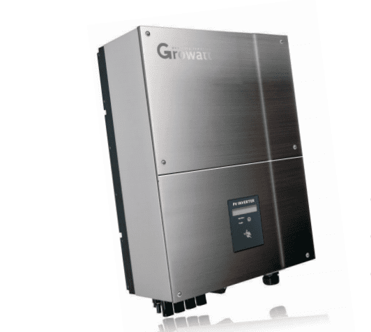
For a Chinese-manufactured brand, Growatt MTL solar inverter can perform better than its Chinese counterparts, add to that that it is cheaper than European inverters on the market.

Still, there are several factors that can affect inverters and it is inevitable to see some issues every now and then. To help you, we have put together a list of fault displays and possible action from Growatt MTL Solar Inverter user manual.

Should any problems arise on your Growatt MTL solar inverter, the LED on the front panel will be red and the LCD displays the relevant information. If you decide to follow the recommended actions below, please note that safety measures should be observed to avoid any risk of injury or you may also seek assistance from a qualified electrician.

Fault

Display

Possible Action

SYSTEM FAULT Ground I Fault 1. The ground current is too high.

2. Unplug the inputs from the PV generator and check the peripheral AC system.

3. After the cause is cleared, re-plug the PV panel and check PV-Inverter status.

4. If the problem persists please call service.

Isolation Fault 1. Check the impedance is between PV (+) & PV (-) and the PV-Inverter is earthed. The impedance must be greater than 8M.

2. If the problem persists please call service.

No Utility 1. Grid is not connected.

2. Check grid connection cables.

3. Check grid usability.

PV Over Voltage 1. Check the open PV voltage; see if it is greater than or too close to 600VDC.

2. If PV voltage is less than 600VDC, and the problem still occurs, please call local service.

Consistent Fault 1. Disconnect PV (+) or PV (-) from the input, restart the PV-Inverter.

2. If it does not work, call service.
> If there is no display on the panel, please check PV-input connections. If the voltage is higher than 150V, call your local service.

> During periods of little or no sunlight, the PV-Inverter may continuously start up and shut down. This is due to insufficient power generated to operate the control circuits.


Here are some more fault messages that you may see on the Growatt MTL front panel display.

FAULT DISPLAY OPERATION
System Fault Auto Test Failed Auto test do not pass
No AC Connection No utility; no grid connect
PV Isolation Low Insulation problem
Residual High GFCI Fault
Output High DCI Output current DC, offset too high
PV Voltage High PV panel voltage too high
AC V Outrange Grid voltage out of range
AC F Outrange Grid frequency out of range
Inverter Fault Error: 100 2.5 V Reference Voltage Fault
Error: 101 Communication Fault
Error: 102 Consistent Fault
Error: 116 EEPROM Fault
Error: 117 Relay Fault
Error: 118 Init Model Fault
Error: 119 GFCI Device Damage
Error: 120 HCT Fault
Error: 121 Communication Fault
Error: 122 Bus Voltage Fault


The full information is available in the Growatt MTL solar inverter manual’s troubleshooting section.

If following the steps above does not fix the issue and your Growatt MTL inverter is still within the warranty period you can contact the equipment installer or supplier.  If your inverter is outside the warranty period we suggest that you contact a professional solar power expert. If you’re on the Gold Coast or Brisbane area contact Gold Coast Power Solutions here and we will be in touch to provide you with further assistance.

Image may be NSFW.
Clik here to view.
Need a quality solar inverter? We deliver Australia wide

Got A Question About Solar Power? Click Here For Answers!

The post Growatt MTL Solar Inverter Fault & Error Messages appeared first on Gold Coast Solar Power Solutions.

JFY JSI Solar Inverter Fault & Error Messages

Image may be NSFW.
Clik here to view.
JFY JSI Solar Inverter
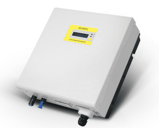
JFY JSI Solar Inverter is a Chinese-manufactured brand so it can be expected that it is way cheaper compared to European inverters on the market.  Several factors may affect an inverter’s performance which may result in failures.

We have put together a list of fault displays and possible action from JFY JSI Solar Inverter’s user manual for your convenience.

If any problems arise, the “Alarm” LED on the front panel will be red and the LCD displays the relevant information. Please note that safety measures should be observed to avoid any risk of injury or you may also seek assistance from a qualified electrician.

DISPLAY

HOW TO DO?

No any display in LCD or LED Check PV-input connections
W01 No grid Check grid connection cables.
W02 Vin overvoltage Check the Voc of PV string, see if it is greater than or too close to max. input DC voltage of relative inverter type.
E01 Isolation error Check the impedance is between PV (+) & PV (-) and the PV-Inverter is earthed. The impedance must be greater than 2MΩ
E02 Ileak error The leakage current is too high.Unplug the inputs from the PV string and check the peripheral AC system.
E03 Grid fault Make sure grid voltage and frequency meet the specifications.

Please note that during periods of little or no sunlight, the JFY JSI Solar Inverter may continuously start up and shut down. This is due to the insufficient power generated to operate the control circuits but this is not a trouble. Here are some more fault messages that you may see on the JFY JSI front panel display.

FAULT DISPLAY COMMENTS
System fault Auto Test Failed Auto Test does not pass
W01 No grid No Utility, No Grid Connect
W02 Vin overvoltage PV panel Voltage is too high
E01 Isolation error Insulation Problem of PV panel
E02 Ileak error GFCI Fault, leakage current is too high
E03 Grid fault Grid voltage/frequency is out of range
Inverter fault E04 Coherence error Consistent Fault
E05 Over temperature Internal temperature abnormal
E06 Relay failure Output relay Fault
E07 DCinj failure Output Current DC Offset too high
E08 EEPROM failure EEPROM Fault
E09 Com. failure Communication Fault
E10 DC bus OV. DC Bus over-voltage
E11 DC bus UV. DC Bus under-voltage
E12 Vref error 2.5V Reference Voltage Fault
E13 DC sensor fault DC current sensor fault
E14 GFCI failure GFCI Device is damaged

The full details are available in the JFY JSI solar inverter manual’s troubleshooting section.

If following the steps above does not fix the issue and your JFY JSI Solar Inverter is still within the warranty period you can contact the equipment installer or supplier. If your inverter is outside the warranty period we suggest that you contact a professional solar power expert. If you’re on the Gold Coast or Brisbane area contact Gold Coast Power Solutions here and we will be in touch to provide you with further assistance.

Image may be NSFW.
Clik here to view.
Need a quality solar inverter? We deliver Australia wide

Got A Question About Solar Power? Click Here For Answers!

The post JFY JSI Solar Inverter Fault & Error Messages appeared first on Gold Coast Solar Power Solutions.


JFY SunTwins Solar Inverter Fault & Error Messages

Image may be NSFW.
Clik here to view.
JFY SunTwins Solar Inverter
JFY SunTwins Solar Inverter has a dual-string series of inverters which aims to provide a much better experience.

However there are several factors that may affect an inverter’s performance and cause failures, hence we have put together a list of fault displays and possible action from JFW SunTJFY Suntwins user manualwin’s user manual for your convenience.

If any problems arise, the “Alarm” LED on the front panel will be red and the LCD displays the relevant information. Please note that safety measures should be observed to avoid any risk of injury or you may also seek assistance from a qualified electrician.

DISPLAY

HOW TO DO?

No any display in LCD or LED Check PV-input connections
W01 No grid Check grid connection cables.
W02 Vin overvoltage Check the Voc of PV string, see if it is greater than or too close to max. input DC voltage of relative inverter type.
E01 Isolation error Check the impedance is between PV (+) & PV (-) and the PV-Inverter is earthed. The impedance must be greater than 2MΩ
E02 Ileak error The leakage current is too high.Unplug the inputs from the PV string and check the peripheral AC system.
E03 Grid fault Make sure grid voltage and frequency meet the specifications.

Please note that during periods of little or no sunlight, the JFY SunTwins Solar Inverter may continuously start up and shut down. This is due to the insufficient power generated to operate the control circuits but this is not a trouble. Here are some more fault messages that you may see on the JFY SunTwins front panel display.

FAULT DISPLAY

COMMENTS

System fault Auto Test Failed Auto Test does not pass
W01 No grid No Utility, No Grid Connect
W02 Vin overvoltage PV panel Voltage is too high
E01 Isolation error Insulation Problem of PV panel
E02 Ileak error GFCI Fault, leakage current is too high
E03 Grid fault Grid voltage/frequency is out of range
Inverter fault E04 Coherence error Consistent Fault
E05 Over temperature Internal temperature abnormal
E06 Relay failure Output relay Fault
E07 DCinj failure Output Current DC Offset too high
E08 EEPROM failure EEPROM Fault
E09 Com. failure Communication Fault
E10 DC bus OV. DC Bus over-voltage
E11 DC bus UV. DC Bus under-voltage
E12 Vref error 2.5V Reference Voltage Fault
E13 DC sensor fault DC current sensor fault
E14 GFCI failure GFCI Device is damaged

The full details are available in the JFY SunTwins Solar Inverter manual’s troubleshooting section.

If following the steps above does not fix the issue and your JFY SunTwins inverter is still within the warranty period you can contact the equipment installer or supplier. If your inverter is outside the warranty period we suggest that you contact a professional solar power expert. If you’re in the Gold Coast or Brisbane area contact Gold Coast Power Solutions here and we will be in touch to provide you with further assistance.

Image may be NSFW.
Clik here to view.
Need a quality solar inverter? We deliver Australia wide

Got A Question About Solar Power? Click Here For Answers!

The post JFY SunTwins Solar Inverter Fault & Error Messages appeared first on Gold Coast Solar Power Solutions.

KLNE SunTeams Solar Inverter Fault & Error Messages

KLNE SunTeams Solar Inverter Image may be NSFW.
Clik here to view.
KLNE SunTeams Solar Inverter
If your KLNE SunTeams Solar Inverter does not operate normally, you will observe that a fault will be showing up on its display screen and the LED will be lit at the same time. We have put together a list of causes and remedy for these faults from KLNE SunTeams Solar Inverter user manual.

It is recommended to do the following actions for quick troubleshooting.

However if there are any uncertainties in performing these measures it is advisable to seek assistance from a qualified electrician to avoid any risk of further damage or injury.

No.

Cause

Remedy

1 <Disconnect Grid>
Possible causes:
Stop power supply from the grid;
AC circuit breaker is disconnected; The both sides of AC circuit breaker are in poor contact.
Idenitfy whether the grid stops power supply;
Identify whether the AC circuit breaker is closed;
Identify whether the breakover of the two terminals of AC circuit breaker is good;
If there are no above problems, please contact your distributor or customer service department.
2 <Grid V Fault>
Possible causes:
The grid voltage exceeds the scope prescribed in the local regulations.
When reporting error, check whether the grid voltage of the inverter is within the range prescribed in local regulations; Report this problem to the distributor or customer service department.
3 <Grid F Fault>
Possible cause:
The grid frequency exceeds the scope prescribed in the local regulations.
Whether this problem is always existing or intermittently existing; Report this problem to the distributor or customer service department.
4 <Low Isolation>
Possible causes:
The ground wires at the AC terminal are in poor contact.
Check whether the ground wire of AC is in good contact; If there is no problem, please contact your distributor or customer service department.
5 <High PV Voltage>
The actual voltage at the DC side exceeds the specified range of the inverter.
Check whether the actual voltage at the DC side is within the specified range of the inverter;  If complying with the range of the inverter voltage, please contact the distributor or customer service department.
6 <High Ground I>
The possible cause is that there is leakage at the AC side.
Disconnect the circuit breakers at the DC side and AC side and check whether there are damages to the cables and circuit breakers at the AC side.
7 <High Temperature>
The ambient temperature of the inverter is too high.
Idenitfy whether the ambient temperature is abnormal; Identify whether the inverter has sufficient heat dissipation space; Identify whether cooling fin of the inverter is blocked; If the external environment is normal, please contact the distributor or customer service.

Here are some more fault messages that you may see on the KLNE SunTeams Solar Inverter display screen and their descriptions.

Fault

Display

Operation

System Fault Disconnect Grid Disconnect Grid
Grid V Fault Grid voltage out range
Grid F Fault Grid frequency out range
Low Isolation Low input isolation
High PV Voltage PV input voltage high
High Ground I GFCI active
High Temperature Temperature too high
Inverter Fault EEPROM Damaged EEPROM has problem
Please initiate System has not been initiated at the first time
GFCI Damaged GFCI device damaged
Sensor Damaged Output AC sensor damaged
SCI Damaged The communication between the two MCU fault
Not Consistent The data is not the same for the two MCU
High DC INJ Output DC Injection Too High
Relay Damaged Output Relay Failure
High Bus Voltage DC Bus Voltage Is Too High
Auto Test Failed Auto test failed
2.5 V Ref Fault 2.5 V Reference Voltage Inside has problem

You may view the full information on KLNE SunTeams solar inverter manual’s troubleshooting section. If following the steps above does not fix the issue and your KLNE SunTeams Solar Inverter is still within the warranty period, unfortunately the KLNE subsidiary in Australia had now been placed in liquidation and any warranty is no longer being honored.

It may be best to get a replacement unit should the problem persist instead of having it repaired where you pay more than $500 and still be left with an inverter of inferior quality without warranty. If you’re in the Gold Coast or Brisbane area contact Gold Coast Power Solutions here and we will be in touch to provide you with further assistance.

Image may be NSFW.
Clik here to view.
Need a quality solar inverter? We deliver Australia wide

Got A Question About Solar Power? Click Here For Answers!

The post KLNE SunTeams Solar Inverter Fault & Error Messages appeared first on Gold Coast Solar Power Solutions.

Solar Immersion Calculator

Surcharge

Clenergy SPH solar inverter blank screen

Blank Screen on Clenergy SPH Solar Inverter – What can you do?

Image may be NSFW.
Clik here to view.
Need a quality solar inverter? We deliver Australia wide

[contact-form-7]Image may be NSFW.
Clik here to view.
Blank screen on your Clenergy SPH solar inverter

At Gold Coast Solar Power Solutions we’ve seen a number of blank screen instances with the Clenergy SPH solar inverter where the screen is just blank – there’s no lights on and nothing is showing on the display. If the screen and lights on your inverter are all blank there are a number of possible causes as follows, it could be a problem with the:

  • Solar Panels
  • DC wiring on the roof
  • DC wiring between the roof and the inverter
  • DC isolator on the roof
  • DC isolator at the inverter
  • DC plugs underneath the inverter
  • Solar Inverter

Blank Screen on your Clenergy SPH Solar Inverter? Try this.

As you probably start to realise from looking at this list this is a fault that is most likely going to require the assistance of an accredited solar electrician such as Gold Coast Solar Power Solutions but before running to the phone or shooting us an email check the following:

  • Solar DC isolator beside the inverter is turned ON
  • DC plugs underneath the inverter are connected firmly and are in good condition

If you’ve checked the solar DC isolator is definitely ON and still the inverter display is blank you are going to need professional help. If you’re near the Gold Coast or Brisbane areas just leave your details on the form on this page or you can contact us here. If you are somewhere else around Australia we recommend finding a local, reputable company with a long history in solar power to help.

Need more information on the Clenergy SPH solar inverter? Checkout the below.

For more information on Clenergy SPH solar inverters including inverter datasheets, manuals, fault codes etc. click here.

Image may be NSFW.
Clik here to view.
Need a quality solar inverter? We deliver Australia wide

Got A Question About Solar Power? Click Here For Answers!

The post Clenergy SPH solar inverter blank screen appeared first on Gold Coast Solar Power Solutions.

Clenergy SPH Solar Inverter Slave Flash Error

Do you have a Clenergy SPH Solar Inverter Slave Flash Error?

Image may be NSFW.
Clik here to view.
Need a quality solar inverter? We deliver Australia wide

[contact-form-7]Image may be NSFW.
Clik here to view.
Clenergy SPH solar inverter slave flash error

A Clenergy SPH Solar Inverter Slave Flash error is a common issue that we see with the Clenergy SPH brand of solar inverters.

With this issue both the Power-On and Status light are off and the Slave Flash message is displayed on the screen. According to the Clenergy SPH solar inverter manual the Slave Flash message means that the internal program is updating the Slave CPU through the RS232 interface. That’s what the manual says however when we have seen the Slave Flash message nothing is connected to the RS232 communication interface and it’s an internal fault with the inverter.

If you Clenergy SPH solar inverter is showing a Slave Flash message on the screen you need to do something about it ASAP as you’re solar power system isn’t operational.

What can you do about a Clenergy Solar Inverter Slave Flash issue?

Try to reboot the system by following the proper shutdown procedure as shown below:

  1. Turn off the SOLAR SUPPLY MAIN SWITCH or the Inverter AC Isolator (if applicable).
  2. Turn off the PV Array DC Isolator located at the inverter.
  3. Wait for approximately 1 minute.
  4. Turn on the SOLAR SUPPLY MAIN SWITCH or AC Isolator (if installed).
  5. Turn on the PV ARRAY DC Isolator.
  6. Wait a few minutes for the inverter to restart.
  7. Check to see if the error has cleared.

If the fault continues, check if your Clenergy SPH solar inverter is still within the 5-year warranty from the installation date so a warranty claim can be made on the inverter. To make a warranty claim you will need to provide proof of purchase in the form of a tax invoice or Certificate of Compliance from when it was originally installed along with the model and serial numbers found on the top of the inverter.

If you need further assistance with your Clenergy SPH Solar Inverter Slave Flash issue and you are in the Gold Coast or Brisbane area please leave your details on the form on this page – we’ll be in touch ASAP to provide you with further assistance. If you need a replacement inverter and you’re somewhere else in Australia please click on the link below; we have quality replacement inverters in stock ready to deliver to your door with FREE freight.

Image may be NSFW.
Clik here to view.
Need a quality solar inverter? We deliver Australia wide

Need more information on Clenergy solar inverters? Checkout the below.

For more information on Clenergy solar inverters including Clenergy inverter datasheets, manuals, fault codes etc. click here.

Click here to get your solar power system back saving you money rather than costing you money!

Got A Question About Solar Power? Click Here For Answers!

The post Clenergy SPH Solar Inverter Slave Flash Error appeared first on Gold Coast Solar Power Solutions.

Clenergy SPH Solar Inverter SCI Fault

Do you have a Clenergy SPH Solar Inverter SCI Fault Message?

Image may be NSFW.
Clik here to view.
Need a quality solar inverter? We deliver Australia wide

[contact-form-7]Image may be NSFW.
Clik here to view.
Clenergy SPH solar inverter SCI Fault

The Clenergy SPH Solar Inverter SCI Fault is a common issue that we see with the Clenergy SPH brand of solar inverters.

Usually with this issue the red Status light is ON and the SCI Fault message is displayed on the screen. According to the Clenergy SPH solar inverter manual the SCI Fault message means that the Internal Master / Slave CPU’s have developed a communication fault. The SCI Fault is an internal fault with the inverter.

If you Clenergy SPH solar inverter is showing a SCI Fault message on the screen you need to do something about it ASAP as you’re solar power system isn’t operational.

What can you do about a Clenergy Solar Inverter SCI Fault issue?

Try to reboot the system by following the proper shutdown procedure as shown below:

  1. Turn off the SOLAR SUPPLY MAIN SWITCH or the Inverter AC Isolator (if applicable).
  2. Turn off the PV Array DC Isolator located at the inverter.
  3. Wait for approximately 1 minute.
  4. Turn on the SOLAR SUPPLY MAIN SWITCH or AC Isolator (if installed).
  5. Turn on the PV ARRAY DC Isolator.
  6. Wait a few minutes for the inverter to restart.
  7. Check to see if the error has cleared.

If the fault continues, check if your Clenergy SPH solar inverter is still within the 5-year warranty from the installation date so a warranty claim can be made on the inverter. To make a warranty claim you will need to provide proof of purchase in the form of a tax invoice or Certificate of Compliance from when it was originally installed along with the model and serial numbers found on the top of the inverter.

If you need further assistance with your Clenergy SPH Solar Inverter SCI Fault issue and you are in the Gold Coast or Brisbane area please leave your details on the form on this page – we’ll be in touch ASAP to provide you with further assistance. If you need a replacement inverter and you’re somewhere else in Australia please click on the link below; we have quality replacement inverters in stock ready to deliver to your door with FREE freight.

Image may be NSFW.
Clik here to view.
Need a quality solar inverter? We deliver Australia wide

Need more information on Clenergy solar inverters? Checkout the below.

For more information on Clenergy solar inverters including Clenergy inverter datasheets, manuals, fault codes etc. click here.


Click here to get your solar power system back saving you money rather than costing you money!

Got A Question About Solar Power? Click Here For Answers!

The post Clenergy SPH Solar Inverter SCI Fault appeared first on Gold Coast Solar Power Solutions.


Macsolar Solar Inverter Fault & Error Messages

Image may be NSFW.
Clik here to view.
Macsolar Solar Inverter
The proper installation of a Macsolar Solar Inverter would prolong its life. However, should there be any internal issues with the inverter this will be detected by the device and cause the Fault light to be displayed permanently. If the red light is on or if there is a green light without the yellow Run light a manual shutdown procedure is recommended.

There are also other faults that may require additional procedures. To make these more accessible, we have put together a list of faults, messages and possible actions from Macsolar Inverter user’s manual. If you are not very keen in performing below procedures, we recommend that you contact a qualified electrician to assist you.

Error No.

Information Message

Corresponding Action

0 Grid Vtg. Fault The grid voltage has exceeded the
permitted range according to local
grid regulations.
Following  causes  might  lead  to
this error:
• Grid voltage is too high or too  low  at  the  point  of common  coupling to the inverter.
• Grid impedance at the terminal of the inverter is too high.
For safety consideration, the
inverter will disconnect itself from
the grid for a short period of time,
and  it  will  reconnect  to  the  grid
automatically after a short period
of time if the grid voltage is back
to the permitted range.
• Check the grid voltage.
• Check the grid connection
of the inverter.
If  the  grid  voltage  exceeds  the permitted  range  because  of  local grid  conditions,  please  ask  the utility operator if the voltage can be adjusted at the feed-in point or if  changes  in  the  values  of  the monitored  operational limits are possible.
If the grid voltage that checked is within the permitted range, yet this error is still showing in the LCD screen, please contact Macsolar Serviceline.
  Grid Vtg.10min Fault The average grid voltage over 10 minutes   has   been   outside   the permitted range according to local grid regulations.
Following causes might  lead  to this error:
• Grid voltage is too high at the point   of   common coupling to the inverter.
• Grid impedance at the terminal of the inverter is too high.
For safety consideration, the inverter will disconnect itself from the grid for a short period of time, and it will reconnect to the grid automatically after a short period
of time if the grid voltage is back
to the permitted range.
•   Check the grid voltage.
• Check the grid connection
of the inverter.
If  the  grid  voltage  exceeds  the permitted  range  because  of  local grid  conditions,  please  ask  the utility operator if the voltage can be adjusted at the feed-in point or if  changes  in  the  values  of  the monitored  operational possible.
If the grid voltage that checked is within the permitted range, yet this error is still showing in the LCD screen, please contact
Serviceline.
2 Fac Fault The grid frequency has left the
permitted range.
For safety consideration, the
inverter will disconnect itself from
the grid for a short period of time,
and  it  will  reconnect  to  the  grid
automatically after a short period
of  time  if  the  grid  frequency  is
back to the permitted range.
• Within safety scope, check
the grid frequency and observe how often major deviations occur.
If  there  are  repeated  frequency turbulences  which  lead  to  this error,   please   ask   the   utility operator  if  modification  of  the operating parameter is possible.
If this error is not solvable, please contact Macsolar Serviceline.
3 Utility Loss The inverter has detected an error
in the cabling and cannot connect
to the grid.
Following causes might  lead  to
this error:
• Grid connection installation
failure.
• Cabling failure.
• Incorrect country setting.
• Check AC installation.
• Check grid connection.
•   Check if the country setting
is correct:
– Via LCD screen (please
refer to chapter 7.2
“Configuration”).
– Via the remote
communication:  setting
Parameter “Country”.
If this error is not solvable, please
contact Macsolar Serviceline.
4 High DC Bus The voltage of the Bus which
paralleling connected   with the
string is too high.
Following causes  might  lead  to
this error:
•   The DC   input   voltage
connected to the inverter is
too high.
• Sudden DC surge.
For safety consideration, the
inverter will shutdown itself.
• Please
disconnect the inverter
from the PV strings (see
chapter   6.5   “DC   side
Disconnection”)  or  else
the inverter might be
damaged.
• Check the  DC  voltage  of
the strings for adherence to
the maximum input voltage
of the inverter, before you
reconnect the inverter to
the PV strings.
5 GFCI Fault The inverter has detected a ground
fault in the PV generator.
• The installer of the PV
generator must solve the
ground  faults before you
re-connect the strings.
If this error is not solvable, please
contact Macsolar Serviceline.
6 Over-temperature  The   delivered   power   of   the
inverter was reduced below rated
power because   of abnormal
temperature within 0.5s.
Following causes  might  lead  to
this error:
•   At least one or more of the
thermally monitored
varistors are defective.
• Overheating inside.
• Not sufficient ventilation.
If this event occurs often:
• Please   ensure   sufficient
ventilation.
• Check the varistors.
If this error is not solvable, please
contact Macsolar Serviceline.
7 Varistor Fault At least one of the varistors from
the DC or AC  side  is  defected.
Following causes might  lead  to
this error:
• Varistor is bust due to contact Macsolar Serviceline. over-voltage protection.
If this event occurs:
Please  check  the  varistors
as   chapter   5.6   “Check
Varistors”.
If this error is not solvable, please
8 PV-Overvoltage The   DC   input   voltage   which
connects to the inverter is too high.
Following causes  might  lead  to
this error:
• The open-circuit voltage of
the PV generator is higher
than the maximum DC
input voltage    of the
inverter.
• Sudden DC surge.
• Junction temperature of
solar panel too low.
• Please immediately
disconnect the inverter
from the PV strings (see
chapter   6.5   “DC   side
Disconnection”)  or  else
the   inverter   might   be
damaged.
Check  the  DC  voltage  of
the strings for adherence to the
maximum input voltage of the
inverter, before you reconnect
the inverter to the PV strings.
9 Consistence Fault Following  causes  might  lead  to
this error:
• Interference device
If this event occurs often:
Please contact Macsolar
Serviceline.
10 Isolation Fault There  is  a  sudden  isolation  fault
which is detected by the inverter.
Normally this fault will only exist
for a very short period of time and
shall not have any bad influence to
the inverter.
If this event occurs often:
Please contact Macsolar
Serviceline.
11 DC INJ Fault The direct component of the AC
current  is  out  of  the  permitted
range.
If this event occurs often:
Please contact Macsolar
Serviceline.
12 Device Fault A  fault  has  occurred  in  one  or
more  major  components  of  the
inverter.
For safety consideration, the
inverter will shutdown itself.
If this event occurs:
Please contact Macsolar
Serviceline.
13 GFCI Device Fault The  internal  sensor  has  detected
that  the  GFCI  Device  is  out  of
function.
For safety consideration, the
inverter will shutdown itself.
If this event occurs:
Please contact Macsolar
Serviceline.
14 Comm. disturbed A fault has occurred in the internal
communication  of  the inverter.
However,  the inverter continues
feeding into the grid.
If this event occurs often:
Please contact Macsolar
Serviceline.
15 Current Sensor Fault A  fault  has  occurred  in  one  or
more current sensor of the inverter.
For safety consideration, the
inverter will shutdown itself.
If this event occurs:
Please contact Macsolar
Serviceline.
16 CPU Ref 2.5V Fault The CPU voltage that detected by
internal sensor is deviating the pre-
set 2.5V reference line.
If this event occurs:
Please contact Macsolar
Serviceline.
17 EEPROM R/W Fail Internal device fault.
For safety consideration, the
inverter will shutdown itself.
If this event occurs:
Please contact Macsolar
Serviceline.
18  DC INJ Device Fault A fault has occurred in the sensor
which detects the direct component
of the AC current.
For safety consideration, the
inverter will shutdown itself.
If this event occurs:
Please contact Macsolar
Serviceline.
19 Relay Fault A fault has occurred in the relay
which will automatically
disconnect  the  inverter  from  the
grid.
For safety   consideration,   the
inverter will shutdown itself.
If this event occurs:
Please   contact Macsolar
Serviceline.
20 AC-Overcurrent The   detected   AC   current   has
exceeded  the  pre-set  Max.  AC
Current.
Following  causes  might  lead  to
this error:
•   Short circuit happens in the
output circuit.
If this event occurs often:
Please contact Macsolar
Serviceline.

The full details are available in the Macsolar Inverter manual’s troubleshooting section. In case performing the steps above does not fix the issue and your Macsolar Solar Inverter is still within the warranty period you can contact the equipment installer or supplier.

If your Macsolar Solar Inverter is outside the warranty period we suggest that you contact a professional solar power expert. If you’re in the Gold Coast or Brisbane area contact Gold Coast Power Solutions here and we will be in touch to provide you with further assistance.

Image may be NSFW.
Clik here to view.
Need a quality solar inverter? We deliver Australia wide

Got A Question About Solar Power? Click Here For Answers!

The post Macsolar Solar Inverter Fault & Error Messages appeared first on Gold Coast Solar Power Solutions.

Samil SolarRiver Inverter Fault & Error Messages

Image may be NSFW.
Clik here to view.
Samil SolarRiver Inverter
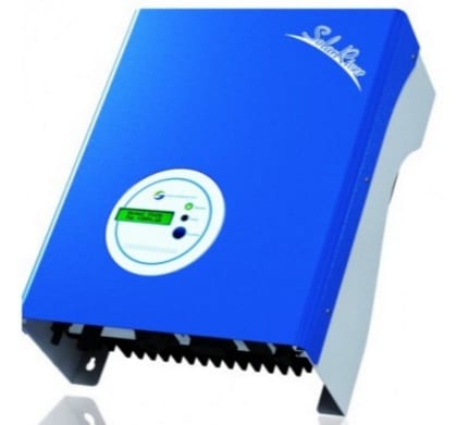
When a fault occurs on your Samil SolarRiver Inverter it is important to check the warning or fault message. This will provide information on the next steps to take.

We have put together a list of faults, diagnosis and solutions from Samil Inverter user’s manual to easily identify and solve most problems that could occur with the Samil SolarRiver Inverter series inverters. Ensure that you follow safety precautions before performing below procedures.  It is also recommended that you contact a qualified electrician to assist you.

Faults

Diagnosis and Solutions

Grid Faults -Waiting for one minute, grid will go back to normal working state.
-Making sure that grid voltage and frequency complies with standards.
-Or, please seek for help from us.
No Utility -Off to grid.
-please check grid-connection, like wire, interface, etc.
-Checking grid usability.
-Or seek for help from us.
PV Over Voltage -Checking the panel’s open-circuit voltage whether the value similar Or already >Max.DC voltage.
-Please seek help from us when voltage ≤ Max.DC voltage.
DC INJ High -DC injection is higher than the set value.
-Wait for one minute.
-Please seek for help from us if it does not go back to normal state.
SCI Failure -Disconnect PV (+), PV (-) with DC input, and re-connect them.
-Please seek for help from us if it cannot go back to normal state.
DC Sensor Fault -Disconnect PV (+), PV (-) with DC input, and re-connect them.
-Please seek for help from us if it cannot go back to normal state.
Isolation Fault -Check the impedance among PV (+), PV (-) and ground.
SR1K5TLA1~SR5KTLA1 >1Mohm
-Please seek for help from us if it cannot be detected or the impedance value is not big enough.
Consistent Fault -Disconnect the PV (+), PV (-) with DC input, then reconnect them.
-Please seek for help from us if it cannot go back to normal state.
Fan Fault – Check the fan whether it is blocked.
-Check the wire of fan whether it is normal.
-Please seek for help from us if it cannot go back to normal state.
Relay Failure -Disconnect the PV (+), PV (-) with DC input, then reconnect them.
-Please seek for help from us if it cannot go back to normal state.
Ground I Fault -Leakage current is too high.
-Disconnect DC and AC connector, check the surrounding equipment on the AC side.
-Reconnect the input connector and check the state of inverter after troubleshooting.
-Please seek for help from us if it cannot go back to normal state.
EEPROM Failure -Disconnect the PV (+), PV (-) with DC input, then reconnect them.
-Please seek for help from us if it cannot go back to normal state.
High DC Bus -Disconnect the PV (+), PV (-) with DC input, then reconnect them.
-Check L line and N line to see whether it has connection faults.
-Please seek for help from us when this fault happens.
GFCI Failure -Disconnect the PV (+), PV (-) with DC input, then reconnect them.
-Please seek for help from us if it cannot go back to normal state.

The full details are available in the Samil Inverter manual’s troubleshooting section. In case performing the steps above does not fix the issue and your Samil SolarRiver Inverter is still within the warranty period you can contact the equipment installer or supplier.  Contact Samil Power Customer Service for further assistance.

Please be prepared to describe the details of your system installation and provide the model and serial number of the unit. If your Samil SolarRiver Inverter is outside the warranty period we suggest that you contact a professional solar power expert. If you’re in the Gold Coast or Brisbane area contact Gold Coast Power Solutions here and we will be in touch to provide you with further assistance.

Image may be NSFW.
Clik here to view.
Need a quality solar inverter? We deliver Australia wide

Got A Question About Solar Power? Click Here For Answers!

The post Samil SolarRiver Inverter Fault & Error Messages appeared first on Gold Coast Solar Power Solutions.

SEA Orion Solar Inverter Fault & Error Messages

Image may be NSFW.
Clik here to view.
SEA Orion Solar Inverter
In the event of a problem with the SEA Orion Solar Inverter, the red fault LED will turn on, the green power light is off and the LCD will display a message identifying the cause of the fault.  Take note of the fault to diagnose the problem in your SEA Orion Solar Inverter.

To easily determine the solutions to these faults, we have put together a list of LCD fault messages, diagnosis and solutions from the SEA Orion Inverter user’s manual.  Please follow safety precautions before performing below procedures.  It is also recommended that you contact a qualified electrician to assist you.

The following are descriptions on the common system and inverter faults on a SEA Orion Solar Inverter:

OPERATING CONDITIONS

MESSAGE

DESCRIPTION

System Faults

Isolation failure Isolation fault There is an electrical fault between the PV panels or wiring and protective
earth, or the input surge suppression circuitry on the SPG-360-2K0-1 has
been damaged due to a lightning surge. This alarm will be displayed on initial
application of PV power. The inverter will not attempt to connect to the AC
mains grid until this fault is rectified.
GFCI active Ground I Fault There has been excessive leakage current from the PV array to the earth while
the inverter was generating power. The inverter has disconnected from the
grid due to this fault.
Grid failure Grid Fault The AC mains grid voltage or frequency is outside of limits (default 206V/264V,
49.25Hz/50.75Hz). The inverter has disconnected from the grid.
No utility No utility The AC mains grid is not available. There has been a mains power failure or the AC mains grid has been turned off.
Input voltage too high PV over voltage The input voltage VPV is greater than 500V on one of the inputs.

Inverter Faults

Consistent failure Consistent fault The readings of the two internal microprocessors do not agree.
Temperature too high Over temperature Internal temperature is excessive.
Output relay failure Relay failure One of the grid connection relays is faulty.
Output DC injection too high. DC INJ High The inverter is generating excessive DC current on the AC mains grid.
EEPROM problem EEPROM Failure The EEPROM memory inside the inverter has a data access problem
Communication failure between microprocessors SCI Failure The communications between the two microprocessors has failed.
DC bus voltage too high High DC Bus The internal DC bus voltage is higher than expected.

Here are the diagnoses and solutions to these faults:

Type

LCD Message

Diagnosis and Solution

System Isolation Fault 1. There is an electrical fault between the PV panels or wiring and protective earth or the
input surge suppression circuitry on the SPG-360-2K0-1 has been damaged due to a
lightning surge.
2. Turn off the PV array main switch, the solar supply main switch and the AC isolation
device (if present).
3. Unplug the PV inputs from the inverter.
4. Turn on the PV array main switch.
5. Measure the following three voltages supplied by the PV array using a multimeter with
a 10MΩ input resistance:
a.   PV+ to PV-
b.  PV+ to protective earth
c.   PV- to protective earth
6. Confirm that b+c is much less than a.
7. If b+c is approximately equal to a, there is an electrical fault in the array. Carefully
inspect all PV panels and array wiring for damaged insulation.
8. Temporarily connect a 1kΩ 10W resistor between + and – on each inverter input.
9. With the 1kΩ resistors in 8 connected, check the DC resistances between each PV
Wait until the voltages across these resistors are all less than 1V.
System Ground I Fault 1. There has been excessive leakage current from the PV array to the earth while the
inverter was generating power. This fault can occur sometimes during heavy rainfall
or if there is heavy condensation on the PV arrays, due to increased leakage currents
between the arrays and earth via this water. If this is the case, once the array has
dried off, the fault should clear.
2. If there has not been any water on the PV array, there is an electrical fault between
the PV panels or wiring and protective earth or the input surge suppression circuit on
the SPG-360-2K0-1 has been damaged due to a lightning surge. Perform the tests in
“Isolation Fault” above.
System Grid Fault 1. Wait for 5 minutes. If the grid returns to normal, the inverter will automatically restart.
2. Measure the grid voltage and frequency and confirm that they are within the
over/under voltage and over/under frequency limits for the inverter. The factory
programmed limits are 264Vrms, 206Vrms, 50.75Hz and 49.25Hz respectively;
however, the local utility may have required these to be changed at system
commissioning
System No Utility 1. The AC mains grid has been disconnected.
2. Check that AC mains voltage is present at the main switchboard and the distribution
board to which the SPG-360-2K0-1 is connected.
3. Check that the solar supply main switch and AC isolation device (if present) are turned
on.
4. Check the connections to the inverter’s AC output cable.
System PV over voltage 1. Check that the PV input voltage is less than 500Vdc.
2. If less than 500Vdc and the fault persists, contact SEA service.
Inverter Fault Over temperature 1. Check that the inverter heat sink is clean and free from debris.
2. Reduce the ambient temperature by improving ventilation around the inverter.
3. If the fault persists, contact SEA service.
Inverter Fault GFCI Failure 1. Turn off the PV array main switch, the solar supply main switch and the AC isolation
device (if present).
2. Leave these switches off for at least one hour.
3. Turn the PV array main switch, the solar supply main switch and the AC isolation
device (if present) back on. The fault should reset.
4. If the fault persists, contact SEA service.
Inverter Fault High DC Bus 1. Check that the AC mains grid L (Active) and N (Neutral) leads have not been reversed.
2. Turn off the PV array main switch, the solar supply main switch and the AC isolation device (if present).
3. Leave these switches off for a few seconds.
4. Turn the PV array main switch, the solar supply main switch and the AC isolation
device (if present) back on. The fault should reset.
5. If the fault persists, contact SEA service.
Inverter Fault Consistent fault
Relay failure
DC INJ High
EEPROM Failure
SCI Failure
Low DC Bus
Ref 2.5V Fault
DC Sensor Fault
1. Turn off the PV array main switch, the solar supply main switch and the AC isolation
device (if present).
2. Leave these switches off for a few seconds.
3. Turn the PV array main switch, the solar supply main switch and the AC isolation
device (if present) back on. The fault should reset.
4. If the fault persists, contact SEA service.

The full details are available in the SEA Orion Solar manual’s troubleshooting section. In case performing the steps above does not fix the issue and your SEA Orion Solar Inverter is still within the warranty period you can contact the equipment installer or supplier.

Please be prepared to describe the details of your system installation and provide the model and serial number of the unit. If your SEA Orion Solar Inverter is outside the warranty period we suggest that you contact a professional solar power expert. If you’re in the Gold Coast or Brisbane area contact Gold Coast Power Solutions here and we will be in touch to provide you with further assistance.

Image may be NSFW.
Clik here to view.
Need a quality solar inverter? We deliver Australia wide

Got A Question About Solar Power? Click Here For Answers!

The post SEA Orion Solar Inverter Fault & Error Messages appeared first on Gold Coast Solar Power Solutions.

Sharp JH1600e Solar Inverter Fault & Error Messages

Image may be NSFW.
Clik here to view.
Sharp JH1600e Solar Inverter
A Sharp JH1600e Solar Inverter would usually show an error or event code to specify a fault. We listed these codes from Sharp Solar Inverter user’s manual to give you an idea of these errors and what can be done about them.

You can refer to the table below for the list of errors and faults in your inverter.

Type

Code

Items

Utility abnormal F -00 Utility over-voltage
F -01 Utility under-voltage
F -02 Utility frequency over
F -03 Utility frequency under
F -06 Anti-islanding (frequency over)
F -07 Anti-islanding (frequency under)
F -08 Miss utility synchronal lock signal
F -09 Freq. abnormal (50<->60 Hz)
PV array abnormal PV array under voltage (<60 V)
P-11 PV array over voltage (>320 V)
Inverter abnormal E15         d-15 Relay sticking
E16         d-16 Communication error
E17         d-17 Aux-power abnormal
E18 Ground fault
d-20 Temperature sensor broken
E21         d-21 Output over current
E22         d-22 DC offset over rating
E23         d-23 Fin high temperature
E26         d-26 DC/DC converter abnormal
E27         d-27 Relay open
E28 DC bus voltage abnormal
EEPROM d-40 EEPROM abnormal

The codes that start with F- are usually caused by the power from the street (the grid) being outside the Sharp JH1600e Solar Inverter’s operating parameters.  The inverter codes beginning with P specify that the voltage coming from the solar panels is outside the inverter parameters. The error that starts with E- signifies a more serious error.  If this continues it changes to a d code. When this happens, a manual shutdown procedure is necessary.

If your Sharp JH1600e Solar Inverter is still within the warranty period you can contact the equipment installer or supplier should the error persists. If your inverter is outside the warranty period we suggest that you contact a professional solar power expert. If you’re in the Gold Coast or Brisbane area contact Gold Coast Power Solutions here and we will be in touch to provide you with further assistance.

You can also check other information in the Sharp JH1600e inverter manual’s Troubleshooting section to learn more on how to fix some errors on your own.

Image may be NSFW.
Clik here to view.
Need a quality solar inverter? We deliver Australia wide

Got A Question About Solar Power? Click Here For Answers!

The post Sharp JH1600e Solar Inverter Fault & Error Messages appeared first on Gold Coast Solar Power Solutions.

SolarKing Solar Inverter Fault & Error Messages

Image may be NSFW.
Clik here to view.
SolarKing Solar Inverter
When your SolarKing Solar Inverter does not operate normally, you will observe that a fault will be shown up on its display screen and the red fault light will be lit at the same time.

We have put together a list of faults and possible actions from SolarKing Inverter user’s manual. If there are any uncertainties in performing these measures it is advisable to seek assistance from a qualified electrician to avoid any risk of further damage or injury.

Display

Possible Actions

System Fault

Isolation Fault 1. Check the impedance between PV (+) & PV (-) and earth ground.
The impedance must be larger than 8M .
2. If above action is useless, the isolation detection circuit fails, replace one unit.
Ground I Fault 1. This is caused by too high ground current.
2. Unplug PV generator from the input, check AC peripheral system.
3. After the cause is cleared, plug PV input again. Check the status of the inverter.
4. If above actions are useless, the GFCI circuit fails, replace one unit.
Grid Fault 1. Wait for 30 seconds, if the grid come back to normal, inverter will start again automatically.
2. Make sure grid voltage and frequency meet the specifications.
3. Use PCM solar control to adjust operation range.
4. If above actions are useless, replace one unit.
Impedance
Fault
1. Grid impedance higher than the permissible value.
2.Wait for 30 seconds, see if it works again.
3.Check the wires between inverter and grid. Change larger wires if necessary.
4.Adjust impedance parameter by PCM solar control program.
5. If useless, the impedance circuit inside failure, please replace another one.
No Utility 1. Grid is not connected; check the AC connection by multi-meter.
2. Check grid connection, such as wire and connector to the inverter.
3. Check breaker between inverter and grid; if it is tripped, DO NOT CLOSE again, replace another unit.

Inverter Failure

PV Over Voltage 1. Check the PV open voltage, see if it is more than or too close to 500VDC.
2. If PV voltage is much less than 500VDC (e.g. <430V), measure the DCV by multi-meter, compare the readings on meter and LCD, if >5%, replace another unit.
Consistent Fault 1. It is caused by the reading between main and redundant controllers are different.
2. Disconnect PV (+) or PV (-) from the input, start the unit again.
3. If this does not work, replace another one.
Device Fault 1. Caused by improper operation of the circuit.
2. Disconnect PV (+) or PV (-) from the input, start the unit again.
3. If it does not work, replace another one.
Over Temperature 1. The internal temperature is higher than specified normal value.
2. Reduce the ambient temperature by some other ways or move inverter to cooler place.
3. If it is not effective, the temperature sensors fails, replace another one.

Here are some error codes that you may see on the SolarKing Solar Inverter and its descriptions.

Error Message

Description

No Utility No AC Line
PV Over Voltage PV Voltage is too high
DC Bus High Dc bus voltage is  too high
DC Bus Low Dc bus voltage is  too low
Over Temperature Temperature is too high
Grid Fault Grid Voltage or Grid Frequency is wrong
Device Fault Hole sensor, GCFI Device
or AD Reference Voltage Fault
Isolation Fault PV Panel isolation problem
Impedance Fault Grid Impedance Fault
Ground I Fault Output ground leakage current too high
Relay Failure OutputRelay Fail
DC INJ High Output DC injection too high
Ref 2.5V Fault 2.5V reference voltage inside problem
DC Sensor Fault Output DC sensor abnormal
GFCI Fault GFCI detection problem
Sci Fault Communication between Master and Slave problem
Consistent Fault The value of Master and Slave are not the same
EEPROM Fault Eeprom problem
Grid V     Mismatch The Grid V of Master and Slave are mismatch
Grid F      Mismatch The Grid F of Master and Slave are mismatch
Grid Z      Mismatch The Grid Impedance of Master and Slave are mismatch
GCFI         Mismatch The GCFI value of Master and Slave are mismatch
DC Curr Mismatch The Output DC current of Master and Slave are mismatch

You may view the full information on SolarKing manual’s troubleshooting section. If following the steps above does not fix the issue and your SolarKing Solar Inverter is still within the warranty period you can contact the equipment installer or supplier.  If your SolarKing Solar Inverter is outside the warranty period we suggest that you contact a professional solar power expert. If you’re in the Gold Coast or Brisbane area contact Gold Coast Power Solutions here and we will be in touch to provide you with further assistance.

Image may be NSFW.
Clik here to view.
Need a quality solar inverter? We deliver Australia wide

Got A Question About Solar Power? Click Here For Answers!

The post SolarKing Solar Inverter Fault & Error Messages appeared first on Gold Coast Solar Power Solutions.

Viewing all 203 articles
Browse latest View live