Quantcast
Channel: All posts Archives - Gold Coast Solar Power Solutions
Viewing all 203 articles
Browse latest View live

Aero-Sharp Data Sheets, Manual and common errors

$
0
0

Aero-Sharp Solar Inverters

Aero-Sharp Data Sheets, Manual and common errors

Aero-Sharp Data Sheets, Manual and common errorsUnfortunately the Aero-Sharp company is no longer trading in Australia which means if you have an issue or fault with your Aero-Sharp inverter you won’t be able to get any assistance from the manufacturer.

Faulty AeroSharp Inverter? Click here for your options.
Aero-Sharp Inverter User Manual (Aero-Sharp data sheet included)
AeroSharp Inverter Fault Codes

Common Aero-Sharp Solar Inverter Errors and Faults

Aero-Sharp Solar Inverter fault light On
Aero-Sharp Solar Inverter 0W power output
Aero-Sharp Solar Inverter Grid Volt Error

The post Aero-Sharp Data Sheets, Manual and common errors appeared first on Gold Coast Solar Power Solutions.


APS Solar Micro Inverters data sheet and manual

CMS Solar Inverters data sheet, manual and common errors

$
0
0

CMS / Carbon Management Solutions Solar Inverters

CMS Solar Inverters data sheet, manual and common errors
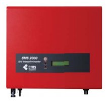
CMS, or Carbon Management Solutions went into voluntary administration back in 2013 which means if you have a CMS 1500 or CMS 2000 solar inverter unfortunately you won’t be able to get any assistance from the manufacturer in the event of a fault code being displayed. Carbon Management Solutions has now merged into a “new entity”, Carbon Management Solutions Group Pty Ltd. They will not honour any of their old warranties but will happily sell you their new you beaut inverters if you’re game…

CMS Solar Inverters data sheet, manual and common errors

Faulty CMS 1500 or CMS 2000 Inverter? Click here for your options.
CMS 1500 and 2000 Inverter Manual
CMS 2000 Data Sheet
CMS 1500 and 2000 Inverter Fault Codes

Common issues with CMS Solar Inverters

CMS 2000 solar inverter Blank Screen – Inverter dead

Carbon Management Solutions did change their name to “CMS Group”, it seems to avoid the warranties on the CMS 1500 and CMS 2000 inverters. Under the new entity “CMS Group” they did release some new inverters, the CMS 1500SS, CMS 3000SS, CMS 5000SS and CMS 10000SS.

CMS 1500SS Data Sheet
CMS 3000SS Data Sheet
CMS 5000SS Data Sheet
CMS 10,000SS Data Sheet

The post CMS Solar Inverters data sheet, manual and common errors appeared first on Gold Coast Solar Power Solutions.

Delta Solar Inverters data sheets, manuals and common errors

$
0
0

Delta Solar Inverters data sheets, manuals and common errors

Delta Electronics, the manufacturer of Delta solar inverters is a massive company. The early Delta Solivia solar inverters had a 10 year warranty as standard, the newer range of Delta solar inverters have a 5 year warranty as standard.

Delta Solar Inverters data sheets, manuals and common errors

Delta Solar Inverters data sheets, manuals and common errorsDelta Solivia Inverter Fault Codes and error messages

Delta Solivia Solar Inverter datasheets

Download the Delta Solivia 2.5 solar data sheet here
Download the Delta Solivia 3.0 solar data sheet here
Download the Delta Solivia 3.3 solar data sheet here
Download the Delta Solivia 5.0 solar data sheet here

Delta Solivia Solar Inverter User Manuals

Download the Delta Solivia 2.5 solar inverter manual here
Download the Delta Solivia 3.0 solar inverter manual here
Download the Delta Solivia 3.3 solar inverter manual here
Download the Delta Solivia 5.0 solar inverter manual here

Common issues with Delta Solivia Solar Inverters

Delta Solivia solar inverter AC Relay Failure
Delta Solivia solar inverter AC Voltage Failure
Delta Solivia solar inverter Blank Screen – Inverter dead

Delta RPI Home Series Solar Inverter datasheets


Delta RPI H3 Datasheet
Delta RPI H3A H4A H5A Datasheet
Delta RPI M6A Datasheet

The post Delta Solar Inverters data sheets, manuals and common errors appeared first on Gold Coast Solar Power Solutions.

Sunny Roo / Beyond Building data sheets, manual and common errors

$
0
0

Sunny Roo Solar Inverters were also rebadged as Beyond Building Solar Inverters

For Beyond Building Inverters please see Sunny Roo as Sunny Roo inverters were also badged as Beyond Building products – they are exactly the same.
Sunny Roo / Beyond Building data sheets, manual and common errors

Sunny Roo / Beyond Building data sheets, manual and common errors

Sunny Roo solar inverters were from the same manufacturer as the Sunna solar inverter, actually they were pretty much the same inverter with a different badge and so like the Sunna inverter the manufacturer is no longer around to honor any warranties. Beyond Building solar inverters are also just rebadged Sunny Roo products so the information below should apply there as well.

Sunny Roo solar inverter data sheet (all models)

Sunny Roo solar inverter user manual

Sunny Roo solar inverter fault and error codes and messages

Common Sunny Roo Solar Inverter Fault / Error Codes

Sunny Roo solar inverter AL05 fault message
Sunny Roo solar inverter AL07 fault message
Sunny Roo solar inverter AL14 fault message
Sunny Roo solar inverter Er00 error message
Sunny Roo solar inverter Er19 error message
Sunny Roo solar inverter Er22 error message
Sunny Roo solar inverter Er29 error message
Sunny Roo solar inverter Isolation Fault error message

The post Sunny Roo / Beyond Building data sheets, manual and common errors appeared first on Gold Coast Solar Power Solutions.

Eaton Solar Inverters manual and common fault and error messages

$
0
0

Eaton Solar Inverters

Eaton ETN2000 solar inverter manual and datasheetEaton Solar Inverters manual and common fault and error messages.

Eaton is a very large company which dabbled in residential solar power inverters for a very short period of time. They still produce very large solar inverters but not inverters that most people will ever see.
Eaton ETN 2000 2kW solar inverters came with a standard 5 year warranty.

Eaton Solar Inverters manual and common fault and error messages

Eaton solar inverter fault and error messages

Download the Eaton ETN2000 solar inverter manual here

The post Eaton Solar Inverters manual and common fault and error messages appeared first on Gold Coast Solar Power Solutions.

Eversolar / Zeversolar inverter data sheets manual and common faults

$
0
0

Eversolar / Zeversolar Solar Inverters

The Eversolar company began in 2007 and soon became one of the biggest solar inverter manufacturers in China. The company changed its name to Zeversolar and at the end of 2012 the SMA Group purchased a 72.5% stake in the company and now SMA fully own the company. This has allowed Zeversolar to combine the best of two worlds: Chinese efficiency and German quality standards.

The early Eversolar inverters did have a few issues but since the SMA Group took a majority stake in the company the German engineers have gone through all the products and ironed out out the issues. Both Eversolar and Zeversolar inverters come with a standard 5 year warranty.

Eversolar inverter data sheets manual and common faults

Eversolar / Zeversolar inverter data sheets manual and common faults

Eversolar Solar Inverter Data Sheets

Eversolar Eversol & Evershine Inverter Data Sheets
Eversol TL1000/1500/2000/3000/3680/5000 Inverter Data Sheets

Eversolar Solar Inverter User Manuals

Eversolar Eversol TL1500, TL2000 Inverter Manual
Eversol TL1500-20, TL2000-20, TL3000-20 Solar Inverter Manual

Common Eversolar Solar Inverter Fault / Error Codes

Eversolar solar inverter Relay Check Fail error message
Eversolar solar inverter DC INJ High error message
Eversolar solar inverter Isolation Fault error message
Eversolar solar inverter Utility Loss error message

The post Eversolar / Zeversolar inverter data sheets manual and common faults appeared first on Gold Coast Solar Power Solutions.

Enphase Solar Micro Inverters data sheets manuals

$
0
0

Enphase Solar Micro Inverters

Enphase was the first company to successfully commercialise the microinverter on a wide scale, and remains the market leader.
The M175 was their first product, released in 2008. The early Enphase micro inverters were plagued with high failure rates. Subsequent models have proved more reliable.
Enphase Solar Micro Inverters data sheets and manuals
Up to 10 year warranties are offered by Enphase.

Enphase Solar Micro Inverters data sheets and manuals

Enphase Solar Micro Inverter Data Sheets

Enphase M215 and M250 Micro Inverter Data Sheet
Enphase S230 Micro Inverter Data Sheet
Enphase S270 Micro Inverter Data Sheet

Enphase Solar Micro Inverter User Manuals

Enphase M215 and M250 Micro Inverter Manual
Enphase S230 and S270 Micro Inverter Manual

The post Enphase Solar Micro Inverters data sheets manuals appeared first on Gold Coast Solar Power Solutions.


Effekta solar inverter data sheet manual and common error codes

$
0
0

Effekta Solar Inverters

Effekta solar inverter data sheet manual and common error codes

The Effekta inverters are made in China and the Effekta company is no longer represented in Australia. Unfortunately there is no warranty support for the Effekta range of inverters. The ES series of Effekta inverters are virtually identical to the SunnyRoo solar inverters. As they were made in the same factory in China, it seems that the original Sunny Roo inverters were direct copies of the Effekta ES inverter series.  The same fault codes and errors apply to both types of inverters.

Effekta solar inverter data sheet manual and common error codes

Effekta solar inverter data sheet manual and common error codes

Effekta solar inverter datasheet
Effekta solar inverter user manual
Effekta solar inverter fault and error codes and messages

Common Effekta Inverter Error Codes

Effekta solar inverter AL05 fault message
Effekta solar inverter AL07 fault message
Effekta solar inverter AL14 fault message
Effekta solar inverter Er00 error message
Effekta solar inverter Er19 error message
Effekta solar inverter Er22 error message
Effekta solar inverter Er29 error message
Effekta solar inverter Isolation Fault error message

The post Effekta solar inverter data sheet manual and common error codes appeared first on Gold Coast Solar Power Solutions.

Isolator ratings calculator

Zeversolar Error Code 38

$
0
0

Zeversolar Error Code 38

solax isolation fault messageIs your Zeversolar Solar Inverter showing an Error Code 38 message?

When your Zeversolar solar inverter is operating correctly the inverter light will be solid green. When the light is red it indicates that your inverter has detected a fault with the system – the particular fault details are displayed on the screen, and if you’re reading this I bet you’re seeing an Error Code 38 message and it’s quite likely that your inverter is beeping at you.

Zeversolar Error Code 38 Message – What does it mean?

An Error Code 38 message on your Zeversolar inverter is telling you that the system has detected leakage of electricity to earth, and this condition is called an earth fault or an isolation fault. The following list is some of the common causes of this type of faults that would make your Zeversolar inverter display an Error code 38 message:

  • Moisture ingress in the solar panels
  • Moisture ingress in the cabling, plugs, isolators or inverter
  • Damage to cables in the solar power system

If you’re seeing an Error Code 38 message the first thing we recommend you try is a reboot of your solar power system.

Get help from Gold Coast Solar Power Solutions by filling out this solar inverter help form

Rebooting Your SolaX Solar Inverter

It is possible that the error you’re seeing with your Zeversolar inverter is just a glitch which will be fixed by a system reboot. To reboot your Zeversolar solar inverter please follow these steps:

  1. Turn OFF the solar supply main switch (or inverter AC isolator if present).
  2. Turn OFF the PV array DC isolator.
  3. Wait for the inverter screen to go completely blank and the red fault light to turn off.
  4. Turn ON the PV array DC isolator.
  5. Turn ON the solar supply main switch (or inverter AC isolator if present).
  6. Wait a few minutes while the inverter boots back up.

If after restarting the inverter you still see the error message “Error Code 38” unfortunately it looks like you may have an issue with your system which is going to require professional help. We recommend you get in touch with a local solar accredited electrician to carry out some fault finding on your system and advise you further. If you are in South East QLD somewhere near the Gold Coast or Brisbane area we will be happy to help.

For further advice please complete the form above under the URGENT heading and we’ll assist you further.

Need service for your solar power system?

Need a quality solar inverter? We deliver Australia wide

Got A Question About Solar Power? Click Here For Answers!

Learn more about solar power battery storage here

Sungrow SG5K-D Error Codes

$
0
0

Sungrow SG2-8K solar inverterThe Sungrow SGK-D solar inverter is a good option if you are on a tight budget. This Chinese solar inverter brand offers a standard 5-year warranty on parts and labor plus an additional 5-year parts only warranty. The inverter also allows monitoring of real-time performance through your iPhone or Android phone with the iSolarCloud App.

In case an issue comes up, we have put together a list of error codes, faults and solutions from the Sungrow SG2-8K Solar Inverter user manual. The list describes the fault code and the recommended troubleshooting procedures. When faults occur on the Sungrow SG2-8K-D solar inverter, “Fault” state will be shown in the smartphone application interface.

Please note that the error codes listed below and the inverter user manual are applicable to the following Sungrow inverter models:

  • Sungrow SG2K-S
  • Sungrow SG2K5-S
  • Sungrow SG3K-S
  • Sungrow SG3K-D
  • Sungrow SG5K-D
  • Sungrow SG8K-D

The number on the model code above signifies the kW rating of the inverter with the “S” or “D” signifying whether the inverter has a Single or Dual Maximum Power Point Tracker.

Get help from Gold Coast Solar Power Solutions by filling out this solar inverter help form

Sungrow SG5K-D Error Codes 001 to 85 (Applicable for SG2K to SG8K models)

Code Description Troubleshooting
002 Grid over-voltage. The grid voltage exceeds the protective value. (Stage 1)

1. Check the voltage of the grid.

2. If the grid voltage exceeds the permissible range of inverter protection parameters, ask the utility grid company for a solution.

3. If the grid voltage is within the permissible range, contact Sungrow Service Dept.

003 Transient over-voltage.
The grid transient
voltage exceeds
inverter allowable
upper limit.
1. This is a short-term fault due to grid
condition. Wait a moment for inverter
recovery.
2. If the fault persists, please contact
Sungrow Service Dept.
004 Grid under-voltage.
The grid voltage is
below the protective
value. (stage I)
1. Check the grid voltage.
2. If the grid voltage exceeds the
permissible range of inverter protection
parameters, ask utility grid company for
solution.
3. If the grid voltage is within the
permissible range, contact Sungrow Service
Dept.
005 The grid voltage is too low. 1. This is a short-term fault due to grid condition. Wait a moment for inverter recovery.
2. If the fault still exists, please contact Sungrow Service Dept..
006 The AC output current exceeds inverter allowable upper limit. 1. The inverter will resume if the output current falls below the protection value.
2. If the fault still exists, please contact Sungrow Service Dept..
007 Transient AC overcurrent 1. The inverter will self-recover after several seconds.
2. If the fault still exists, please contact Sungrow Service Dept..
008 The grid frequency
exceeds inverter
allowable upper limit.
1. Check the grid frequency.
2. If the grid frequency exceeds the permissible range of inverter protection parameters, ask
utility grid company for solution.
3. If the grid frequency is within the permissible range, contact Sungrow Service Dept..
009 The grid frequency is below the inverter
allowable lower limit.
010 Islanding 1. Check whether AC circuit breaker is triggered.
2. Check whether AC cables are all firmly connected.
3. Check whether grid is not in service.
4. If all conditions are OK and this fault still occurs in the LCD screen, contact Sungrow Service Dept..
011 The DC component of AC current exceeds inverter limit. 1. Wait a moment for inverter recovery.
2. If the fault occurs repeatedly, contact Sungrow Service Dept..
012 A failure current is
detected.
1. Check the PV strings for ground fault.
2. If the fault occurs repeatedly, contact Sungrow Service Dept..
014 The average grid voltage exceeds the permissible range for over 10 minutes. 1. Wait a moment for inverter recovery.
2. Check the voltage of the grid. If the grid voltage exceeds the permissible range of inverter protection parameters, ask utility grid
company for solution.
3. If the fault occurs repeatedly, contact Sungrow Service Dept..
015 The grid voltage exceeds the permissible range 1. Check the model of the AC cables.
2. Wait a moment for inverter recovery.
3. If the grid voltage exceeds the permissible range, ask utility grid company for solution.
4. If the fault occurs repeatedly, contact Sungrow Service Dept..
016 The bus voltage or power is high. 1. Wait a moment for inverter recovery.
2. If the fault occurs repeatedly, contact Sungrow Service Dept..
019 The transient bus voltage is high.  1. Wait a moment for inverter recovery.
2. If the fault occurs repeatedly, contact Sungrow Service Dept..
020 The bus voltage is high. 1. Wait a moment for inverter recovery.
2. If the fault occurs repeatedly, contact Sungrow Service Dept..
021 PV1 input overcurrent is detected Check the layout and the wiring of PV1 input.
022 PV2 input overcurrent is detected Check the layout and the wiring of PV2 input.
028 PV1 reverse
connection
Check the cable connections of PV1.
029 PV2 reverse
connection
Check the cable connections of PV2.
036 The temperature of
radiator is too high

1. Check whether the placement of inverter is correct.

2. Check whether the inverter operating ambient temperature is more than the range indicated in the specification.

3. Check whether AC output power exceeds the nominal power.

4. If the fault still exists, please contact Sungrow.

037 The internal temperature of inverter is too high
038 Relay fault is detected 1. Wait a moment for inverter recovery.
2. If the fault occurs repeatedly, contact Sungrow Service Dept..
039 The insulation resistance is low. (ISO-flt) 1. Check whether the positive and negative of PV panels is short-circuited with ground lead.
2. Wait a moment for inverter recovery.
3. If the fault occurs repeatedly, contact Sungrow Service Dept..
041 Leakage current self-test abnormality 1. Wait a moment for inverter recovery.
2. If the fault occurs repeatedly, contact Sungrow Service Dept..
043 Inner under-temperature fault.
The ambient temperature inside the inverter is too low.
The inverter will recover once the ambient temperature rises above -25℃.
044 Inverter self-test fault. 1. Wait a moment for inverter recovery.
2. If the fault occurs repeatedly, contact Sungrow Service Dept.
045 PV1 boost circuit fault.
046 PV2 boost circuit
fault.
048 Phase current
sampling fault.
053 The slave DSP detects that the grid voltage exceeds inverter allowable upper limit. 1. Check the grid voltage.
2. If the grid voltage exceeds the permissible range of inverter protection parameters, ask utility grid company for solution.
3. If the grid voltage is within the
permissible range, contact Sungrow ServiceDept.
054 The slave DSP detects that the grid frequency exceeds inverter allowable upper limit. 1. Check the grid frequency.
2. If the grid frequency exceeds the
permissible range of inverter protection parameters, ask utility grid company for solution.
3. If the grid frequency is within the
permissible range, contact Sungrow Service Dept.
056 The slave DSP detects that the leakage current exceeds inverter allowable
upper limit.
1. Check whether there is a grounded fault of the PV string.
2. If the fault occurs repeatedly, contact Sungrow Service Dept.
059 Communication alarm between master DSP and slave DSP. 1. Wait 1 minute for inverter recovery.
2. If the fault persists, contact Sungrow Service Dept
061 Alarm for no inverter type setting. Contact Sungrow Service Dept.
070 Fans are defective Stop the inverter and disconnect the AC & DC cables. Check whether the fan duct has been blocked. If not, replace fans.
084 Warning for reverse
cable connection of the
Sungrow Meter.
1. Check whether the power cable connections are correct.
2. If “Existing Inverter” is set to “ON” via LCD menu, check and ensure that its rated power is correctly set.
3. For Sungrow single-phase meter, check whether the CT clamp of the 1-phase sensor is correctly placed. Refer to “5.6.1 On the Meter Side”
085 Mismatched software version. Please contact Sungrow Service Dept.

Sungrow SG5K Error Codes 100 to 514 (Applicable for SG2K to SG8K models)

Code Description Troubleshooting
100 The AC output current exceeds the upper limit. 1. The inverter will resume if the output current falls below the protection value.
2. If the fault persists, please contact Sungrow Service Dept.
101 Grid over-frequency.
The grid frequency exceeds the protective value, which is higher  han the protective
value of error 008. (stage II)
1. Check the grid frequency.
2. If the grid frequency exceeds the permissible range of inverter protection parameters, ask utility grid company for solution.
3. If the grid frequency is within the permissible range, contact Sungrow Service Dept.
102 Grid under-frequency.
The grid frequency is below the protective value, which is lower than the protective
value of error 009. (stage II)
106 Abnormal grounding. Neither the PE terminal on the AC connection block nor the second PE terminal on the
enclosure is reliably connected.
Check whether there is a reliable inverter grounding line, if there is access to the ground, and the fault persists, please contact Sungrow Service Dept.
200 Bus hardware over-voltage fault. The bus voltage
exceeds the protective value.
1. Wait for inverter recovery after bus voltage lower.
2. If the fault occurs repeatedly, contact Sungrow Service Dept.
201 The bus voltage is too low. 1. Wait a moment for inverter  recovery.
2. If the fault occurs repeatedly,  contact Sungrow Service Dept.
202 PV hardware over-current fault. The PV1 or PV2 current exceeds the protective value. If the fault occurs repeatedly,  contact Sungrow Service Dept.
203 The PV input voltage exceeds the bus voltage. Check the functionality of the PV
connection terminals.
306 Input and output power
mismatching fault.
If the fault occurs repeatedly, contact Sungrow Service Dept.
315 PV1 current sampling fault. Channel sampling anomaly. Contact Sungrow Service Dept.
316 PV2 current sampling fault.
320 Leakage current sensor fault Contact Sungrow Service Dept.
409 All temperature sensors fail. If the fault occurs repeatedly, contact Sungrow Service Dept.
501 External memory reading/writing warning

1. Inverter can normally be connected to the grid.

2. Power on the inverter again. If the fault persists contact Sungrow Service Dept.

503 Ambient temperature sensor open circuit warning. If the fault occurs repeatedly, contact Sungrow Service Dept.
504 Ambient temperature sensor short circuit warning.
505 Radiator temperature sensor open circuit warning.
506 Radiator temperature sensor short circuit warning.
514 Abnormal communication warning of Sungrow meter. (Inverter can be normally connected to the grid).

1. Check whether the power cable connection of the meter is correct.

2. Check whether the RS485 connection is correct.

For further details please check the Sungrow SG2-8K solar inverter manual’s Troubleshooting section. Should you follow the troubleshooting steps above but the issue is not rectified check if it’s still under warranty, if it is you can contact Sungrow for further assistance. Be ready with the serial number, fault name and code with a brief description of the fault.

If your Sungrow SG2-8K solar inverter is outside the warranty period we suggest that you contact a local solar power expert. If you need further assistance please enter your details in the following form.

Get help from Gold Coast Solar Power Solutions by filling out this solar inverter help form

Need a quality solar inverter? We deliver Australia wide
Got A Question About Solar Power? Click Here For Answers!

Learn more about solar power battery storage here

The post Sungrow SG5K-D Error Codes appeared first on .

KNS Marble & Granite 38kW Commercial Solar Power System

$
0
0

KNS Marble & Granite is a local Gold Coast business specialising in stone benchtops. By utilising the latest technology in laser templating, inline polishers, and CNC bridge saws ensures KNS Marble & Granite create a quality product every time. These high-tech tools do however consume a large amount of power. 

As the business has expanded so too have the power bills, which is why Gold Coast Solar Power Solutions were approached to look into a cost-effective solution.

Solaredge monitoring graphOn inspection of the business premises and examination of the electricity accounts, Gold Coast Solar Power Solutions designed a 38.4 kW SolarEdge optimised solar array connected to a SolarEdge 30kW 3 phase inverter to offset the sites weekday power consumption.  The weekday power consumption could have allowed for a slightly larger system however any solar system does require approval from the electricity distributor, in our case Energex, before being connected to the electricity grid. As soon as you go over 30kW of inverter capacity Energex’s requirements for connecting to the grid become a lot more onerous and expensive. A solar system with a 30kW inverter is the sweet spot before expensive grid protection controls, engineering costs, and application fees need to be factored into the costs.

Gold Coast Solar Power Solutions are the business solar power experts

The solar proposal utilising a quality SolarEdge solar inverter and 96 x 400W 144 cell Seraphim Solar panels optimised with SolarEdge P850 power optimisers complete with long warranties was presented to the owner. With the system’s estimated Return on Investment (RoI) of 4 years and estimated power bill savings greater than $200,000 over the next 25 years the green light was given to move forward with the installation.

In December 2020 Gold Coast Solar Power Solutions supplied and installed the 96 Seraphim 400W panels on the business connected to the 3 phase 30kW SolarEdge inverter with zero downtime for the business as the switchboard work, electrical connections, and testing were carried out outside of the normal business hours.

With the installation of a SolarEdge Smart meter, KNS Marble & Granite management are able to keep an eye on how the system is performing and how the consumption of the business is being offset by the solar power system. The SolarEdge monitoring portal also allows Gold Coast Solar Power Solutions to keep a close eye on the performance of the entire system and ensure the very highest yield is achieved for the customer, a win-win for everyone.

Learn more about commercial solar power systems for businesses here.

Read more commercial solar power case studies here.

Click here for a FREE, no obligation quotation for home solar power from your Gold Coast solar power experts.

38kW SolarEdge commercial solar power system at Arundel


Company / Organisation KNS Marble & Granite
Location Arundel, Gold Coast Australia
Installation Date December 2020
Industry Marble & granite benchtops
Solution 96 x 400 W JA Solar Panels
1 x SolarEdge 30kW 3 phase Inverter
48 x SolarEdge P850 Power Optimisers
1 x SolarEdge Smart Meter
Estimated Savings Over 25 Years Over $200,000.00
CO2 Equivalent Abatement per year 51 Tonnes
Energy Output per year 58,867 kWh

Gold Coast Solar Power Solutions are the business solar power experts

The post KNS Marble & Granite 38kW Commercial Solar Power System appeared first on Gold Coast Solar Power Solutions.

Solar Power Helensvale – Paulene’s Testimonial

$
0
0

A large home complete with a swimming pool and ducted air conditioning can be expected to use a lot of power, and the small existing solar power system at this Helensvale property just wasn’t cutting it. Gold Coast Solar Power Solutions removed the existing system and upgraded the property to a 13.32kW system.  This system will more than cover the customers day time consumption, whilst also providing plenty of surplus solar power to offset their nighttime usage.

Paulene from Helensvale: “We were highly impressed with the professional job which was completed in a timely manner by the Gold Coast Solar Power Solutions team. We would recommend them any time.”

Solar power helensvale systemSolar power Helensvale: Paulene’s 13.32kW Solar Power System was proudly installed by Gold Coast Solar Power Solutions in April 2021.

Solar Power Specifications:

  • System Size: 13.32kW
  • System Location: Helensvale, Gold Coast, Queensland, Australia
  • Solar Panel Type & Quantity: Seraphim 370W x 36
  • Solar Inverter: Sungrow SG5K-D x 2

Since 2008 Gold Coast Solar Power Solutions have been installing solar power systems on the Gold Coast and the surrounding areas. Our experienced and friendly team is local to Helensvale and can provide you with no-pressure advice to help determine the best solution for your specific needs. When you have a system installed in the Helensvale area, Gold Coast Solar Power Solutions will liaise with Energex & your electricity retailer for the upgrade of your electricity meter.

We also provide system maintenance checks and solar panel cleaning, solar power system upgrades, and additions, as well as repairs and replacements on solar panels and inverters.

If you’re in the Helensvale area and are after a solar power system, Gold Coast Solar Power Solutions can help you today!

Gold Coast Solar Power Solutions are the residential solar experts

The post Solar Power Helensvale – Paulene’s Testimonial appeared first on Gold Coast Solar Power Solutions.

Robina Solar Power-Simon’s Testimonial

$
0
0

Robina solar power – what about shading? When you’re looking for a solar power system but have shading issues at different times, what do you do? Choose an optimised solar power system from SolarEdge of course! Standard solar panels are connected in series, and when you have shading on one panel it’ll affect the performance of all the other panels it’s connected to. The great thing with SolarEdge is each solar panel is individually optimised, so the shading on one panel doesn’t affect the rest of the system.

Shading. Enemy no.1 of solar panels

Morning shade on solar panels

Robina Solar Panels – Note the morning winter shade

At Simons’ home in Robina there’s a number of large trees that shade the North roof at different times of the day. This shade is especially problematic in the winter when the sun is lower in the sky. As these trees aren’t on Simons’ property, removing or trimming them isn’t really an option. The only viable solution is to try and minimise their effect as much as possible.

Simons’ property is a perfect example of how SolarEdge power optimisers can help achieve maximum performance when shade is an issue. In the pictures you can see how the morning shade in winter is affecting the panels closest to the trees, the other panels however are still working away at full capacity. The lower image is taken from the SolarEdge monitoring portal, it shows how much power each panel is producing. It’s also great for locating faults with solar panels as well.

Solaredge shading

Note the top panels in the shade but that isn’t affecting the other panels as with SolarEdge optimisers they are all working seperately

Simon from Robina: “Great experience from initial enquiry, through quoting and install. Simon, Hiro and Ben and team were all very professional. Communication was constant, install was completed on time without fault. The Solaredge system installed is exceeding our expectations. Thanks again.”

Robina Solar Power: Gold Coast Solar Power Solutions proudly installed Simon’s 10.36 kW back in May of 2021.

Solar Power Specifications:

  • System Size: 10.36 kW
  • System Location: Robina, Gold Coast, Queensland, Australia
  • Solar Panel Type & Quantity: SolarEdge 370W x 28
  • Solar Inverter: SolarEdge 10 kW single-phase inverter

Gold Coast Solar Power Solutions have been installing solar power systems on the Gold Coast and the surrounding areas since 2008. Our team are experienced, friendly, and local to the Robinaare, in fact, our office is just across the highway in Worongary. We are more than happy to provide you with no-pressure advice to help determine the best solution for your individual requirements. When you have a system installed in the Robina area, we liaise with Energex & your electricity retailer for the upgrade of your electricity meter.

We also provide system maintenance checks and solar panel cleaning, solar power system upgrades, additions, along with repairs and replacements on solar panels and inverters. We have hybrid and off-grid battery systems available too!

If you’re in the Robina area and are after a solar power system, Gold Coast Solar Power Solutions can help you today!

Gold Coast Solar Power Solutions are the residential solar experts

The post Robina Solar Power-Simon’s Testimonial appeared first on Gold Coast Solar Power Solutions.


For Approval: Gold Coast Solar

$
0
0

At Gold Coast Solar Power Solutions, we love to see our customers maximise the return on their investment in solar power and the system we recommend to achieve this is a SolarEdge inverter working in conjunction with SolarEdge power optimisers underneath every solar panel.

SolarEdge Background

SolarEdge invented the Power Optimiser which revolutionised the way power is harvested and managed in a solar system. In a SolarEdge installation, each panel is connected to an intelligent electronic chip called a power optimiser. Power optimisers maximise solar energy production from each panel separately and therefore reduce power losses. If an individual panel underperforms, it won’t affect the performance of any of the other panels in the string. The bottom line is SolarEdge Power Optimisers help to harvest more solar power per panel.

Check out this video on how SolarEdge Power Optimisers work

The Complete Residential Solution

SolarEdge is one of the only solar technology providers to offer a complete solution. All products are designed to work together and come with market leading warranties from one manufacturer.

The SolarEdge complete residential solution consists of;

Smart Panels

Premium SolarEdge smart panels, each integrated with a power optimiser, for greater energy production. Elegant black frame design and excellent reliability.

Power Optimisers

ntegrated with SolarEdge smart panels or installed on third-party panels. A power optimiser is designed to optimise the performance of each solar panel to provide greater energy production and enhanced safety.

Change colour to reflect gold coast solar solutions colour scheme

Smart Inverters

Single and three phase inverters supporting every type of residential roof. Inverters are compatible with battery storage and EV charging solutions.

SolarEdge Home Battery

Store unused solar power in the SolarEdge Home Battery for later use. Maximise energy independence with the backup interface to power your home during a grid outage.

Smart Energy

Use excess solar production with a range of smart energy products to power high loads such as heat pumps or pool pumps. Smart Energy products are designed to use more of your solar energy to reduce electricity bills. Smart Energy products can be easily controlled via the mySolarEdge app.

See how SolarEdge performs in Australia

Industry Leading Warranties

SolarEdge inverters come standard with 12- year warranties, which is far longer than a standard solar inverter warranty of 5 years. What’s more, SolarEdge inverter warranties can be extended to an incredible 25 years if the homeowner desires.

SolarEdge power optimisers come standard with a 25-year warranty, which is the same length as the performance warranty on the solar panels they are connected too.

As a SolarEdge Preferred Partner, SolarEdge will assist in covering our labour costs for any warranty work within the relevant warranty period.

Greater System Up Time with Web-Based Performance Monitoring

The mySolarEdge app provides real-time visibility on energy use and production. You can use it to measure and manage solar energy more effectively maximise energy savings and manage activities like electric vehicle or battery charging.

For Gold Coast Power Solutions, we are notified if there is an issue with your solar system, and the detailed performance monitoring even shows us which panel is affected. This helps us diagnose and resolve the issue more efficiently

Greatly Increased Safety Features

Most solar systems sold in Australia can create high uncontrolled DC voltages that can pose a fire risk. Electrical arc faults cause solar fires.
Electrical arc faults are cause by simple things like loose connections, corrosion, water ingress, extreme weather events, rodent damage, and accidental damage.
SolarEdge has a comprehensive safety suite to reduce the risk of electrical arc faults that may cause a fire.

Fronius solar inverter and maximising self consumption

$
0
0

In this article we are going to have a look at how you can get the most out of your Fronius solar inverter by maximising your self consumption.

Power is quite expensive to buy from the grid yet if you have surplus solar power – that’s solar power you’ve produced but aren’t using- you don’t get paid much at all for it.

If you’re not going to be paid much for the power you’ve produced it’s in your best interest to try and use this power yourself by maximising your solar self consumption. With a Fronius inverter there’s a few things you can do to achieve this, starting with the Fronius data manager card, like this one here.

The data manager card is installed inside your inverter and allows it to connect to the Fronius Solar web monitoring portal by wifi or a wired network connection. Solar Web is a free service from Fronius and is a great tool as all the information from your solar power system will be saved and presented in an easy to understand graphical interface.

Another great benefit is that solar web can be set up to send you email alerts of any errors the inverter may have so you can sort out any issues quickly, which means your system will have as little downtime as possible.

With a datamanager card connected you’ll have all the information about what your solar power systems doing but to take this information to the next level you want to combine it with data about your power consumption, and to do that you need a Fronius smart meter like this one here.

The Fronius smart meter is installed in your switchboard and collects all your power consumption data and displays it on the Solar web portal so you can get a good idea about what power your using and when – and when this information is combined with your solar power production data it highlights what you can change in your consumption habits to maximise self use, such as having the pool pump running a bit earlier or turning the washing machine on later in the day.

Here’s an example from our office, as our office fridge isn’t opened after 5pm or before 6am we’ve recently set it on a timer so it turns off at 5pm and starts up again at 6am.

Here you can see the fridge load pulling in and dropping out all night long, but when we installed the timer you can see how our night time standby load has dropped substantially. Just that one little tweak is saving about $100 a year on our power bills as now the fridge is running on free solar power about 95% of the time.

I wouldn’t recommend ever doing this with the fridge in your kitchen at home but it’s certainly a possibility for any storage fridges and freezers which are rarely opened, as if there not opened and are relatively full they tend to keep their temperature quite well when turned off overnight.

When you have a Fronius datamanager card and Fronius smart meter setup there’s a great little function that you can use called the Fronius energy management relay. It’s a function on the data manager card that can be setup to automatically control loads such as pool pumps or hot water systems when certain conditions are met. Say for example you have a hot water system that has a 1.8kW element. We can set it up so that when the inverter sees that 1.8kW of power is being produced surplus to your consumption it automatically turns on the hot water, and if surplus drops below a set amount, say 1.8kw it’ll automatically switch off, ensuring only surplus solar is used to heat your water.

We set this all up through our special control box like this one here:

-it has a 3 position switch that you’d normally leave on auto to run automatically via the Fronius energy management relay, or off to turn the load off altogether, or a bypass mode which bypasses the energy management relay and turns the load such as your pool pump or hot water system on- full time – you would use the bypass mode if say you wanted to clean the pool or if you had visitors staying over and needed more hot water than usual. It’d also be helpful if there was ever a problem with the inverter and the energy management relay wasn’t running properly for whatever reason- as this bypasses it altogether.

The energy management relay also has a function to set a minimum run time per day which is really important for loads such as hot water systems as if you have a miserable day and your solar doesn’t have enough surplus power available you still want hot water! This function works by setting a minimum run time per day and a start time to trigger this function -for example it can be set so that if the hot water hasn’t heated for 3hrs before 3pm it will automatically be turned on to run for however long is still required for the system to run for 3hrs. This is important as it ensures you don’t end up having cold showers! If your using the energy management relay to control a pool pump the number of hours it runs on a miserable day isn’t nearly as important, so for a pool pump this feature could be left off.

Unfortunately at the moment the energy management relay can only be used to control one load, so either a pool or hot water system but not both, however you could have the pool pump connected to the energy management relay and use another device from Fronius to control your hot water called Ohm-pilot.

The ohm pilot is used for resistive loads which are pretty much heating elements as used in traditional electric hot water systems and things like heated towel rails and underfloor heating.

When any surplus power is available at all, even as little as 10watts the ohm pilot will send this surplus power to the resistive load it’s connected too! So you don’t have to wait until the whole 1800w of surplus is available as with the energy management relay, whatever surplus power you have will be utilised. This is a great way to use your hot water system like a battery to store your surplus power for later use as hot water.

Another great benefit of solar web with the Fronius smart meter that’s worth mentioning is that it gives you valuable information about your power consumption in relation to your solar production- this information will help you choose the right sized battery in the future, which is yet another reason why the Fronius smart meter is a fantastic addition to any solar power system with a Fronius inverter.

So you can see by the things we’ve covered that your Fronius inverter is quite a capable piece of equipment and with a few small additions can really help you maximise your solar self consumption which in the long run run will save you even more money on your power bills.

Thanks for watching this video, I hope it helps you get the very best out of your solar power system and if you like what you’ve learnt don’t forget to hit the subscribe button for more helpful solar power information from Gold Coast Solar Power Solutions.

The post Fronius solar inverter and maximising self consumption appeared first on Gold Coast Solar Power Solutions.

Solar Power Battery Storage

$
0
0

Why Solar Power Battery Storage?

You may have heard of solar power battery storage before, but why has it become such a hot topic recently?
The main reason can be found in the following graph.
Residential power consumption can benefit with solar power storage with a Tesla PowerWall
The green area in the graph shows solar power which is generated by the solar power system but hasn’t been required; it’s called surplus power. We buy power at around 25c a kWh so the blue section of the graph is saving 25c a kWh but the green surplus power is being sent back to the grid, usually for only around 6 to 8c a kWh. At that low rate it doesn’t make sense to send surplus power back to the grid, so why not store it in batteries and draw from it when you need it?

How a solar power system with a battery bank works

The term “battery ready solar power system”

For 2016 it looks like it’s the new catch cry of solar power sales people, yes I can assure you that this solar power system is battery ready! But buyer beware, as the term battery ready is a very loose and open ended term, as okay you may one day be able to connect a battery bank to your solar power system but just how much work and additional components will that require? Will it just be a matter of buying a compatible battery bank to connect into the system or will thousands and thousands of additional dollars be required to actually get the battery bank to work with your system?

You see the issue here is that in both cases a solar power system can be called “battery ready” by a sales person but the difference is in how much extra work and components are required to actually get the solar power system working in conjunction with a battery.

What’s required for a solar power battery storage system?

Solar panels – this ones pretty obvious, for a solar power system to be what it is you need solar panels!

Fronius Symo Hybrid Battery Ready Solar InverterHybrid Solar Inverter – for a solar power system to work with batteries you need a hybrid solar inverter – it’s called a hybrid as it’s a standard grid connect inverter but it can also charge and discharge batteries, hence the hybrid name. For 3 phase supplies we recommend the Fronius SYMO hybrid inverter, for single phase systems we recommend the SolarEdge StorEdge solar inverter.

DC Coupled Battery Storage Solar Power Systems
Both these solar inverters are designed to be “DC coupled” to a battery bank such as the Tesla PowerWall; this is the most efficient way to connect a battery bank as the system is designed to take the DC solar power generated by the solar panels and send it onto the batteries as DC power.

AC Coupled Battery Storage Solar Power Systems
Most other solar inverters out there which can connect to battery banks and may be classed as battery ready use what’s called an “AC coupled” system to take the power from your solar panels to the battery. This is quite inefficient as the DC power from the solar panels is converted by the inverter into AC power, then back to DC power to charge the batteries. When the power stored in the batteries is required it is then once again converted from DC to AC for use. Each of these conversions from DC to AC and AC to DC lowers the efficiency of the system which is why it’s not recommended as the best option for a solar power system with battery storage.

A great new device from SMA called the Sunny Boy Storage is an AC coupled system which is separate to your grid connect inverter and can couple to any existing grid connect inverter system to store your surplus power. This product is designed to work with the Tesla PowerWall Home Battery which Gold Coast Solar Power Solutions are certified installers of.

Electricity Meter – this is not your standard meter that your power company reads but a separate electricity meter which communicates with your battery control system to tell Battery ready solar power systems require an electricity meter such as the Fronius smart meter 
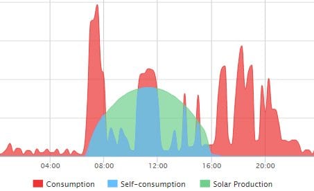
the batteries what to do. It constantly monitors the power consumption of your property and this important data is used to tell the hybrid inverter what to do with the power from the batteries and from the solar panels. If the solar power system is producing more power than your property is consuming it will automatically send the required solar power to be used to power your appliances and send the surplus power to charge the batteries. If the property starts using more power than the solar is providing it will draw the additional power as required from the batteries. Obviously this electricity meter is a crucial component to maximise the self consumption of your solar power; if you are wanting your solar power system to be battery ready we highly recommend installing the electricity meter to suit the battery storage system initially, as the data that this meter provides will help you select the optimum sized battery when you are ready to look at them.

Buyer Beware! An important point to keep in mind

A point that needs raising in regards to battery ready solar power systems is what happens if there’s a blackout and you lose power from the grid? If your intending to put in a battery storage system you’re probably just expecting power will be available from your batteries if the grid goes down – right? Well BEWARE! – this is not necessarily the case!

The battery storage systems such as the SolarEdge StorEdge inverter, Fronius Hybrid, do provide backup power of some essential loads, but beware that quite often this is not the case! It’s worth asking the question as you don’t want to find out when there’s a blackout and you were expecting to have power.

In conclusion – battery ready solar power systems

As we have discussed many standard grid connect solar power systems can be called “battery ready” however if you ever wanted to upgrade the system to actually work with batteries you would be looking at potentially more than $5000 in additional costs to get the system ready to work with batteries; and that cost is before the cost of batteries.

At Gold Coast Solar Power Solutions we highly recommend if you want to install a solar power system that is truly “battery ready” to initially install an inverter system which can be DC coupled to the batteries such as the 3 phase Fronius SYMO hybrid inverter system or the Single phase SolarEdge StorEdge solar inverter. This will be the most efficient system which is ready for any future technological advances – DC coupled systems are the future without a doubt. We also highly recommend installing an electricity meter with the initial installation as it will provide valuable data on your power requirements and will be invaluable in sizing the optimal battery storage to go with your solar power system – a system that is truly battery ready!
Click here for a FREE, no obligation quotation for a battery ready solar power systems from your Gold Coast solar power experts.

Got A Question About Solar Power? Click Here For Answers!

The post Solar Power Battery Storage appeared first on Gold Coast Solar Power Solutions.

Solar Power Example: Incorrectly Sized System

$
0
0


A little while Gold Coast Solar Power Solutions was asked to provide a solar power proposal for a local Gold Coast childcare center which of course we were very happy to do. After submitting our proposal we did not hear from them for a couple of months so we gave them a call. The manager proceeded to tell me that they had signed up with another company for a much larger system than we had proposed. Let’s just look at this situation and the savings this childcare center can expect.

Firstly some background on the current state of solar power feed-in tariffs in QLD. You may or may not be aware that the current QLD solar power net feed-in tariff pays 8c per kWh for any surplus solar; this is the power that the solar power system has produced but has not been used on the property at that moment so it has been sent back to the power grid as surplus electricity to be used next door or where ever it is required. The electricity account holder currently gets paid the feed-in tariff rate of 8c per kWh of surplus power, plus any further incentive that their electricity retailer offers such as those offered by Click Energy.

What you are probably not aware of is some of the finer details of this feed-in tariff which can be found on the website here, mainly as follows:

  • The 8c solar power net feed-in tariff will end on the 30th of June 2014, so customers who are receiving it now will lose it altogether.
  • For a solar power system to be eligible for the 8c solar power net feed-in tariff the inverter capacity cannot exceed 5 kilowatts.With this information in mind I recommended to the owner of the business that we install a power monitoring system for a week to establish how much power was being used at the site and so we could analyze the data and determine the best possible size of solar power system to give the best return for the business, he agreed to this and after a week I had the following data.

    chilcare business days
    The graph above shows the childcare centres power consumption from midnight to midnight on a weekday, a perfect example of a power load suited for a solar power system to cover, averaging around 6 kW during the day.
    childcare weekend
    The graph above shows the childcare centres power consumption from midnight to midnight on a weekend. As the facility is only used on weekdays this is just stand by loads and fridges etc. The average load here is around 1 kW, both day and night.

    Our Solar Power Proposal

    From this data, it is clear to see that a solar power system producing much more than 6 kW of power would be producing a fair amount of surplus solar power to the business’s requirements, and this additional solar power production would be going back to the grid as surplus power at little to no benefit to the business, remembering from the information above that a system with an inverter larger than 5 kW will not be receiving the 8c state feed-in tariff, therefore the maximum they could receive for this surplus power would be 8c per kWh from the electricity retailer AGL; Click Energy pay 10c per kWh but they have their feed-in tariff capped at a 5 kW system as well.

    Taking all this information into account we provided a solar power proposal specifying 30 x quality REC 250W solar panels (7.5kW in total) coupled with an SMA Sunnyboy 5000TL inverter for the following reasons (a side note half the panels were to face NE and half NW):

  • We want as close to 6kW of power being produced as possible.
  • We want to be eligible for the solar power feed-in tariff if possible to ensure maximum return on the investment; keeping the inverter size to 5 kW retains this eligibility so the site can benefit by receiving a higher tariff on weekends.
  • This system will produce 5kW of solar power from 9 am to 3pm most days, nicely matching the sites weekday requirements.
  • Below are the same graphs with an estimated line of solar power input to offset the power consumption.
    graph-with-solarUsing these premium, high performance products our calculations, taking into account the business using all the power produced on weekdays and only 1 kW per hour being consumed on the weekends with surplus going back to the grid on the net feed in tariff came up with the following:
  • Quarterly Savings on Power Bills: $635
  • Yearly Savings on Power Bills: $2,540
  • Expected Pay Back Period: 4 years
  • Expected Savings Over 10 years: $27,000As can be seen this is a very nice return from the investment in solar power and with quality components as specified the customer could expect continued high performance and trouble free operation for much longer than 10 years with free electricity every single day! As I mentioned at the beginning, unfortunately our proposal and the reasoning behind it was not taken into consideration.

    Solar Power System Installed at the Business

    On following up this business about our solar power quotation I was told by the manager that they had gone with another company with a 15 kW system and that they would be selling all the surplus power on the feed in tariff. My alarm bells where ringing!! Let’s look at the immediate issues:

  • The system is way bigger than they actually require
  • They have been lied to, they will not be eligible for the feed in tariff as the system has an inverter larger than 5 kW in size
  • Even if they were eligible for the net feed in tariff it is not in the businesses best interests as they are not paid well for it.Lets have
  • Quarterly Savings on Power Bills: $1050
  • Yearly Savings on Power Bills: $4,200
  • Expected Pay Back Period: 4 years
  • Expected Savings Over 10 years: $27,000
    17500/4200

The post Solar Power Example: Incorrectly Sized System appeared first on Gold Coast Solar Power Solutions.

Delta RPI Home Series Solar Inverter faults & error codes

$
0
0

Delta RPI Home Series Solar Inverter faults

The Delta RPI Home Series range of solar inverters can develop a number of different faults, when a fault is present an error message will be displayed on the screen. Below is a list of error messages, explanations on the error or fault and a list of actions to take to resolve the issue.

If you have one of the error or fault messages below we recommend you follow the listed actions to take to remove the fault before contacting a company who can help you further such as Gold Coast Solar Power Solutions.


Need service for your solar power system?

Delta RPI – M Series inverter faults

Message Possible Cause Action
AC Freq
High
1. Actual utility frequency is over
the OFR setting
2. Incorrect country setting
3. Detection circuit malfunction
1. Check the utility frequency on the inverter
terminal
2. Check country setting
3. Check the detection circuit inside the inverter
AC Freq
Low
1. Actual utility frequency is
under the UFR setting
2. Incorrect country or Grid
setting
3. Detection circuit malfunction
1. Check the utility frequency on the inverter
terminal
2. Check country & Grid setting
3. Check the detection circuit inside the inverter
Grid Quality Non-linear load in Grid and near
to inverter
Grid connection of inverter need to be far away
fromnon-linear load if necessary
HW Connect
Fail
1. Wrong connection in
AC plug
2. Detection circuit malfunction
1. Check the AC connection, must accords to
manual
2. Check the detection circuit inside the inverter
No Grid 1. AC breaker is OFF
2. Disconnect in AC plug
1. Switch on AC breaker
2. Check the connection in AC plug and make
sure it connects to inverter
AC Volt Low 1. Actual utility voltage is under
the UVR setting
2. Incorrect country or Grid
setting
3. Wrong connections in AC plug
4. One or more internal fuses are
broken
5. Detection circuit malfunction
1. Check the utility voltage connection to the
inverter terminal
2. Check country & Grid setting
3. Check the connection in AC plug
4. Replace fuses (FUC1-3) and check all
switching devices in boost & inverter stages
5. Check the detection circuit inside the inverter
AC Volt High 1. Actual utility voltage is over
the OVR setting
2. Utility voltage is over the Slow
OVR setting during operation
3. Incorrect country or Grid
setting
4. Detection circuit malfunction
1. Check the utility voltage on the inverter
terminal
2. Check the utility voltage on the inverter
terminal
3. Check country & Grid setting
4. Check the detection circuit inside the inverter
Solar1 High 1. Actual Solar1 voltage is over
1000Vdc
2. Detection circuit malfunction
1. Modify the solar array setting, and make the
Voc less than 1000Vdc
2. Check the detection circuit inside the inverter
Solar2 High 1. Actual Solar2 voltage is over
1000Vdc
2. Detection circuit malfunction
1. Modify the solar array setting, and make the
Voc less than 1000Vdc
2. Check the detection circuit inside the inverter
Insulation 1. PV array insulation fault
2. Large PV array capacitance
between Plus to Ground or
Minus to Ground or both.
3. Detection circuit malfunction
1. Check the insulation of Solar inputs
2. Check the capacitance, dry PV panel if
necessary
3. Check the detection circuit inside the inverter
Solar1 Low 1. Actual Solar1 voltage is
under the limit
2. Some devices were
damaged inside the inverter
if the actual Solar1 voltage is
close to “0”
3. Detection circuit malfunction
1. Check the Solar1 voltage connection to the
inverter terminal
2. Check all switching devices in boost1
3. Check the detection circuit inside the inverter
Solar2 Low 1. Actual Solar2 voltage is
under the limit
2. Some devices were
damaged inside the inverter
if the actual Solar2 voltage is
close to “0”
3. Detection circuit malfunction
1. Check the Solar2 voltage connection to the
inverter terminal
2. Check all switching devices in boost2
3. Check the detection circuit inside the inverter
HW FAN 1. One or more fans are locked
2. One or more fans are
defective
3. One ore more fans are
disconnected
3. Detection circuit malfunction
1. Remove the object that stuck in the fan(s)
2. Replace the defective fan(s)
3. Check the connections of all fans
4. Check the detection circuit inside the inverter
HW DC
Injection
1. Utility waveform is abnormal
2. Detection circuit malfunction
1. Check the utility waveform. Grid connection of
inverter need to be far away from non-linear
load if necessary
2. Check the detection circuit inside the inverter
Temperature
High
1. The ambient is over 60℃
(The installation is abnormal)
2. Detection circuit malfunction
1. Check the installation ambient and
environment
2. Check the detection circuit inside the inverter
HW NTC1
Fail
1. Ambient temperature >90℃
or <-30℃
2. Detection circuit malfunction
1. Check the installation ambient and
environment
2. Check the detection circuit inside the inverter
(RTM1)
Temperature
Low
1. Ambient temperature is
<-30℃
2. Detection circuit malfunction
1. Check the installation ambient and
environment
2. Check the detection circuit inside the inverter
(RTG1)
HW NTC4
Fail
1. Ambient temperature >90℃
or <-30℃
2. Detection circuit malfunction
1. Check the installation ambient and
environment
2. Check the detection circuit inside the inverter
(RTH1)
HW DSP
ADC1
1. Insufficient input power
2. Auxiliary power circuitry
malfunction
3. Detection circuit malfunction
1. Check the input voltage, must > 150Vdc
2. Check the auxiliary circuitry inside the inverter
3. Check the detection circuit inside the inverter
HW DSP
ADC2
1. Insufficient input power
2. Auxiliary power circuitry
malfunction
3. Detection circuit malfunction
1. Check the input voltage, must > 150Vdc
2. Check the auxiliary circuitry inside the inverter
3. Check the detection circuit inside the inverter
HW DSP
ADC3
1. Insufficient input power
2. Auxiliary power circuitry
malfunction
3. Detection circuit malfunction
1. Check the input voltage, must > 150Vdc
2. Check the auxiliary circuitry inside the inverter
3. Check the detection circuit inside the inverter
HW Red
ADC1
1. Insufficient input power
2. Auxiliary power circuitry
malfunction
3. Detection circuit malfunction
1. Check the input voltage, must > 150Vdc
2. Check the auxiliary circuitry inside the inverter
3. Check the detection circuit inside the inverter
HW Red
ADC2
1. Insufficient input power
2. Auxiliary power circuitry
malfunction
3. Detection circuit malfunction
1. Check the input voltage, must > 150Vdc
2. Check the auxiliary circuitry inside the inverter
3. Check the detection circuit inside the inverter
HW
Efficiency
1. The calibration is incorrect
2. Current feedback circuit is
defective
1. Check the accuracy of current and power
2. Check the current feedback circuit inside the
inverter
HW COMM2 1. Red. CPU is idling
2. The communication
connection is disconnected
1. Check reset and crystal in Red. CPU
2. Check the connection between Red. CPU and
DSp
HW COMM1 1. DSP is idling
2. The communication
connection is disconnected
3. The communication circuit
malfunction
1. Check reset and crystal in DSP
2. Check the connection between DSP and
COMM
3. Check the communication circuit
Ground
Current
1. PV array insulation fault
2. Large PV array capacitance
between Plus to Ground or
Minus to Ground
3. Either side of boost driver or
boost choke malfunction
4. Detection circuit malfunction
1. Check the insulation of Solar inputs
2. Check the capacitance (+ <-> GND & – <->
GND), must < 2.5uF. Install a external
transformer if necessary
3. Check boost driver & boost choke
4. Check the detection circuit inside the inverter
HW Connect
Fail
1. Power line is disconnected
inside the inverter
2. Current feedback circuit is
defective
1. Check the power lines inside the inverter
2. Check the current feedback circuit inside the
inverter
RCMU Fail 1. RCMU is disconnected
2. Detection circuit malfunction
1. Check the RCMU connection inside the
inverter
2. Check the detection circuit inside the inverter
Relay Test
Short
1. One or more relays are
sticking
2. The driver circuit for the relay
malfunction
1. Replace the defective relay(s)
2. Check the driver circuit inside the inverter
Relay Test
Open
1. One or more relays are
abnormal
2. The driver circuit for the relay
malfunction
3. The detection accuracy is not
correct for Vgrid and Vout
1. Replace the defective relay(s)
2. Check the driver circuit inside the inverter
3. Check the Vgrid and Vout voltage detection
accuracy
Bus
Unbalance
1. Not totally independent or
parallel between inputs
2. PV Array short to Ground
3. Driver for boost is defective or
disconnected
4. Detection circuit malfunction
1. Check the inputs connections
2. Check the PV Array insulation
3. Check the driver circuit for boost inside the
inverter
4. Check the detection circuit inside the inverter
HW Bus
OVR
1. Driver for boost is defective
2. Voc of PV array is over
1000Vdc
3. Surge occurs during operation
4. Detection circuit malfunction
1. Check the driver circuit for boost inside the
inverter
2. Modify the solar array setting, and make the
Voc less than 1000Vdc
3. N/A
4. Check the detection circuit inside the inverter
AC Current
High
1. Surge occurs during operation
2. Driver for inverter stage is
defective
3. Switching device is defective
4. Detection circuit malfunction
1. N/A
2. Check the driver circuit in inverter stage
3. Check all switching devices in inverter stage
4. Check the detect circuit inside the inverter
HW CT A
Fail
1. Test current loop is broken
2. CSC1 is defective
3. Detection circuit malfunction
1. Check the connection of WC3 to CNC16
2. Replay CSC1 with new one
3. Check the detection circuit inside the inverter
HW CT B
Fail
1. Test current loop is broken
2. CSC2 is defective
3. Detection circuit malfunction
1. Check the connection of WC3 to CNC16
2. Replace CSC2 with new one
3. Check the detection circuit inside the inverter
HW CT C
Fail
1. Test current loop is broken
2. CSC3 is defective
3. Detection circuit malfunction
1. Check the connection of WC3 to CNC16
2. Replace CSC3 with new one
3. Check the detection circuit inside the inverter
HW AC OCR 1. Large Grid harmonics
2. Switching device is defective
3. Detection circuit malfunction
1. Check the utility waveform. Grid connection of
inverter need to be far away from non-linear
load if necessary
2. Check all switching devices in inverter stage
3. Check the detection circuit inside the inverter
HW ZC Fail The detection circuit for
synchronal signal malfunction
Check the detection circuit for synchronal signal
inside the inverter
DC Current
High
1. Switching device in boost is
defective
2. Driver for boost is defective
3. Input current detection circuit
malfunction
1. Check all switching device in boost
2. Check the driver curcuit for boost inside the
inverter
3. Check input current detection circuit

Delta RPI – H Series inverter faults


Message Possible cause Action
E01: Grid Freq
Over Rating
1. Actual utility frequency is
over the OFR setting
2. Incorrect country setting
3. Detection circuit malfunction
1. Check the utility frequency on the inverter
terminal
2. Check country setting
3. Check the detection circuit inside the
inverter
E02: Grid Freq
Under Rating
1. Actual utility frequency is
under the UFR setting
2. Incorrect country or Grid
setting
3. Detection circuit malfunction
1. Check the utility frequency on the inverter
terminal
2. Check country & Grid setting
3. Check the detection circuit inside the
inverter
E07:Grid
Quality
Non-linear load in Grid and
near to inverter
Grid connection of inverter need to be far
away from non-linear load if necessary
E09: No Grid 1. AC breaker is OFF
2. Disconnect in AC plug
3. Internal fuses are broken
1. Switch on AC breaker
2. Check the connection in AC plug and
make sure it connects to inverter
3. Replace fuses and check all switching
devices in boost & inverter stages
E10: Grid Volt
Under Rating
1. Actual utility voltage is under
the UVR setting
2. Utility voltage is under the
Slow UVR setting during
operation
3. Incorrect country or Grid
setting
4. Detection circuit malfunction
1.&2. Check the utility voltage connection to
the inverter terminal.

3. Check country & Grid setting
4. Check the detection circuit inside the
inverter

E11: Grid Volt
Over Rating
1. Actual utility voltage is over
the OVR setting
2. Utility voltage is over the
Slow OVR setting during
operation
3. Incorrect country or Grid setting
4. Detection circuit malfunction
1.&2. Check the utility voltage on the inverter
terminal

3. Check country & Grid setting
4. Check the detection circuit inside the
inverter

E13: Slow
Over Voltage
Range
1. Actual utility voltage is over
the OVR setting
2. Incorrect country or Grid
setting
3. Detection circuit malfunction
1. Check the utility voltage on the inverter
terminal
2. Check country & Grid setting
3. Check the detection circuit inside the
inverter
E26:Slow Over
Frequency
Range
1. Actual utility frequency is
over the OFR setting
2. Incorrect country or grid
setting
3. Detection circuit malfunction
1. Check the utility frequency on the inverter
terminal
2. Check country setting
3. Check the detection circuit inside the
inverter
E27:Slow
Under
Frequency
Range
1. Actual utility frequency is
under the UFR setting
2. Incorrect country or Grid
setting
3. Detection circuit malfunction
1. Check the utility frequency on the inverter
terminal
2. Check country & Grid setting
3. Check the detection circuit inside the
inverter
E28: Slow
Under Voltage
Range
1. Actual utility voltage is under
the UVR setting
2. Incorrect country or Grid
setting
3. Detection circuit malfunction
1. Check the utility voltage on the inverter
terminal
2. Check country & Grid setting
3. Check the detection circuit inside the
inverter
E30: DC Volt
Over Rating
1. Actual Solar1 voltage is over
550Vdc (RPI-H3) or 1000Vdc
(RPI-H5)
2. Detection circuit malfunction
1. Modify the solar array setting, and make
the Voc less than 550Vdc (RPI-H3) or
1000Vdc (RPI-H5)
2. Check the detection circuit inside the
inverter
E32: L/N
Reversed
1. Incorrect AC wiring
2. Incorrect AC connection
setting
1. Check if brown wire is connected to Line
and blue wire is connected to Neutral.
2. Check display “AC configurat.” setting
A01: DC Offset
Over Rating
1. Utility waveform is abnormal
2. Detection circuit malfunction
1. Check the utility waveform. Grid
connection of inverter need to be far away
from non-linear load if necessary
2. Check the detection circuit inside the
inverter
A05: NTC Over
Temp
1. The ambient temp. is over
60℃
2. Detection circuit malfunction
1. Check the installation ambient and
environment
2. Check the detection circuit inside the
inverter
A06: Inside
NTC Circuit
Fail
1. Ambient temp. >100℃ or
<-24℃
2. Detection circuit malfunction
1. Check the installation ambient and
environment
2. Check the detection circuit inside the
inverter
A08: Heat Sink
NTC1 Fail
1. Boost heat sink temp.
>100℃ or <-24℃
2. Detection circuit
malfunction
1. Check the installation ambient and
environment
2. Check the detection circuit inside the
inverter.
A09: Heat Sink
NTC2 Fail
1. Inverter heat sink temp.
>100℃ or <-24℃
2. Detection circuit malfunction
1. Check the installation ambient and
environment
2. Check the detection circuit inside the
inverter
A15:DSP ADC
Vgrid/Iout Fail
1. Auxiliary power circuitry
malfunction
2. Detection circuit malfunction
1. Check the auxiliary circuitry inside the
inverter
2. Check the detection circuit inside the
inverter
A16:DSP ADC
Vin/Vbus Fail
1. Auxiliary power circuitry
malfunction
2. Detection circuit malfunction
1. Check the auxiliary circuitry inside the
inverter
2. Check the detection circuit inside the
inverter
A17:DSP ADC
Iin/Iboost Fail
1. Auxiliary power circuitry
malfunction
2. Detection circuit malfunction
1. Check the auxiliary circuitry inside the
inverter
2. Check the detection circuit inside the
inverter
A18:RED. ADC
Vgrid Fail
1. Auxiliary power circuitry
malfunction
2. Detection circuit malfunction
1. Check the auxiliary circuitry inside the
inverter
2. Check the detection circuit inside the
inverter
A19:DSP ADC
Iout_dc Fail
1. Auxiliary power circuitry
malfunction
2. Detection circuit malfunction
1. Check the auxiliary circuitry inside the
inverter
2. Check the detection circuit inside the
inverter
A20:
Efficiency Inconsistent
1. The calibration is incorrect
2. Current feedback circuit is defective
1. Check the accuracy of current and power
2. Check the current feedback circuit inside the inverter
A22: Internal
Comm Fault_R
1. DSP is idling
2. The communication
connection is disconnected
3. The communication circuit
malfunction
1. Check reset and crystal in DSP
2. Check the connection between DSP and
COMM
3. Check the communication circuit
A24: Residual
Curr Over
Rating
1. PV array insulation fault
2. Large PV array capacitance
between Plus to Ground or
Minus to Ground
3. Either side of boost driver or
boost choke malfunction
4. Detection circuit malfunction
1. Check the insulation of Solar inputs
2. Check the capacitance (+ <-> GND & –
<-> GND), must < 2.5uF. Install an external
transformer if necessary
3. Check boost driver & boost choke
4. Check the detection circuit inside the
inverter
A25: Ground
Fault
1. PV array insulation fault
2. Large PV array capacitance
between Plus to Ground or
Minus to Ground or both.
3. Detection circuit malfunction
1. Check the insulation of Solar inputs
2. Check the capacitance, dry PV panel if
necessary
3. Check the detection circuit inside the
inverter
A27: RCMU
Circuit Fail
1. RCMU is disconnected
2. Detection circuit malfunction
1. Check the RCMU connection inside the
inverter
2. Check the detection circuit inside the
inverter
A28: Relay
Short
1. One or more relays are
sticking
2. The driver circuit for the
relay malfunction
1. Replace the defective relay(s)
2. Check the driver circuit inside the inverter
A29: Relay
Open
1. One or more relays are
abnormal
2. The driver circuit for the
relay malfunction
3. The detection accuracy is
not correct for Vgrid and Vout
1. Replace the defective relay(s)
2. Check the driver circuit inside the inverter
3. Check the Vgrid and Vout voltage
detection accuracy
A30: Bus
Unbalance
1. Not totally independent or
parallel between inputs
2. PV Array short to Ground
3. Driver for boost is defective
or disconnected
4. Detection circuit malfunction
1. Check the inputs connections
2. Check the PV Array insulation
3. Check the driver circuit for boost inside the inverter
4. Check the detection circuit inside the
inverter
A31: Bus_P
Over Volt
Rating
1. Driver for boost is defective
2. Voc of PV array is over
550Vdc (RPI-H3) or 1000Vdc
(RPI-H5)
3. Surge occurs during
operation
4. Detection circuit malfunction
1. Check the driver circuit for boost inside
the inverter
2. Modify the solar array setting, and make
the Voc less than 550Vdc (RPI-H3) or
1000Vdc (RPI-H5)
3. N/A
4. Check the detection circuit inside the
inverter
A33: Bus_N
Over Volt
Rating
1. Driver for boost is defective
2. Voc of PV array is over
550Vdc (RPI-H3) or 1000Vdc
(RPI-H5)
3. Surge occurs during
operation
4. Detection circuit malfunction
1. Check the driver circuit for boost inside
the inverter
2. Modify the solar array setting, and make
the Voc less than 550Vdc (RPI-H3) or
1000Vdc (RPI-H5)
3. N/A
4. Check the detection circuit inside the
inverter
A35: Bus Volt
Over Rating
1. Driver for boost is defective
2. Voc of PV array is over
550Vdc (RPI-H3) or 1000Vdc
(RPI-H5)
3. Surge occurs during
operation
4. Detection circuit malfunction
1. Check the driver circuit for boost inside
the inverter
2. Modify the solar array setting, and make
the Voc less than 550Vdc (RPI-H3) or
1000Vdc (RPI-H5)
3. N/A
4. Check the detection circuit inside the
inverter
A36:Output
Curr Transient
Over
1. Surge occurs during
operation
2. Driver for inverter stage is
defective
3. Switching device is defective
4. Detection circuit malfunction
1. N/A
2. Check the driver circuit in inverter stage
3. Check all switching devices in inverter
stage
4. Check the detect circuit inside the inverter
A37: AC Curr
Over Rating
Detection circuit malfunction Check the detect circuit inside the inverter
A42: CT
Current Sensor Fail
1.Inverter choke Fail
2.Output Filter Fail
3. Detection circuit malfunction
1. Check Inverter choke inductance.
2. Check output filter capacitance.
3. Check the detection circuit inside the
inverter
A45: HW
OOCP
1. WB1 WB2 misconnection.
2. Detection circuit malfunction
1. Check the connection of WB1 and WB2.
2. Check the detection circuit inside the
inverter
A50:Zero
Cross Circuit
Fail
The detection circuit for
synchronal signal malfunction
Check the detection circuit for synchronal
signal inside the inverter
A56:Hardware
Incompatibility
1. HW power rating incorrect 1. Check comm. HW power rating info.
A60: DC Curr
Over Rating
1. Switching device in boost is
defective
2. Driver for boost is defective
3. Input current detection circuit
malfunction
1. Check all switching device in boost
2. Check the driver circuit for boost inside
the inverter
3. Check input current detection circuit
A70: DC Curr
Transient Over
1. Switching device in boost is
defective
2. Driver for boost is defective
3. Input current detection circuit
malfunction
1. Check all switching device in boost
2. Check the driver circuit for boost inside
the inverter
3. Check input current detection circuit


Get help with your Delta A42 CT Current Sensor Fail message from Gold Coast Solar Power Solutions by filling out this solar inverter help form

Need a quality solar inverter? We deliver Delta A42 CT Current Sensor Fail replacement Australia wide

Got A Question About Solar Power? Click Here For Answers!

Learn more about solar power battery storage here

The post Delta RPI Home Series Solar Inverter faults & error codes appeared first on Gold Coast Solar Power Solutions.

Viewing all 203 articles
Browse latest View live